Steering and Control Systems
The Automatic Pilot
The Automatic Pilot described is the Sperry Marine Model: ADG 300 VT
The helm steering assembly consists of a helm wheel, display assembly, switch assembly and three potentiometers. The potentiometers contained in the unit are driven through the gearing attached to the helm wheel. The helm order is displayed numerically through an overlay switch panel using two 7-segment displays. Lighted arrows below the seven segment displays indicate helm order, direction, and rough magnitude. Helm order is adjustable for maximum rudder angles of 20° to 75°.
The ratio of helm order to wheel angle is variable.
Wheel movement near midships, where fine control is
desirable, gives helm orders similar to that which would be provided by a
conventional helm having approximately four turns hard-over to hard-over. With
this variable ratio helm, however, the ratio of rudder order to helm angle at
higher values, where fine control of the rudder is not required, is increased logarithmically
so that the total range of the rudder travel can be ordered in less that one
full turn of the wheel.
A selection switch on the display assembly allows the
helm to be configured for linear or non linear steering gear. Selection of
non-linear mode allows the installer to calibrate the helm order display, using
trim potentiometers for modifying the displayed helm order to match non-linear
steering gear.
The mode switch input from the steering control system
to the helm steering assembly is used to enable, or disable, the helm order
display. While operating the steering system in the non-helm mode, the PREVIEW
switch allows the helmsman to momentarily display the helm angle, which would
be ordered when the helm is again selected as the controlling device. Dimmer
keys are provided for brightness control. They allow the intensity level of the
displays on the unit to be adjusted when operating the steering system in any
mode.
Helm Wheel
The helm wheel provides helm order inputs to steer the
ship when the HAND mode of steering is selected. The helm wheel allows for 160°
rotation ± 5° in each direction from centre.
The helm wheel is mounted to a shaft equipped with a
gear, which mechanically drives the variable resistors. The helm wheel and the
casting have markings, which show the helm wheels centre position. The hub also
contains hash marks, which show 5° and 10° corresponding to a linear 35° rudder
steering system.
Potentiometers
The three potentiometers are mechanically aligned with
the helm wheel through gearing. Two single potentiometers are used as helm
input for a dual steering system and the third potentiometer provides the helm
angle to the display assembly for displaying the helm order and direction. A
section of the potentiometer provides a steering failure alarm.
Display Assembly
The display assembly is a micro-controller based
circuit board which provides a digital read out of helm order (in degrees). It
contains LED light bars which provide panel illumination of the switch
assembly. The display assembly contains LED light bars, which illuminate behind
arrows on the switch assembly. The arrows indicate the direction wheel rotation
and approximate position (off centre, 1/3, 2/3, and full hard-over). The
display assembly also contains the circuitry for dimming the LEDs, and houses the circuitry for lamp test and helm
advisor functions.
Switch Assembly
The switch assembly contains three switches (PREVIEW,
TEST, and DIMMER), associated legends for the switches and for the HELM ORDER LEDs, and eight indicator arrows that are illuminated by
LED light bars on the display assembly (four for port and four for starboard).
Back-panel lighting of the switch assembly is supplied by LEDs
mounted on the display assembly.
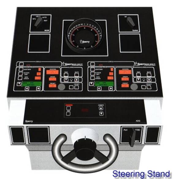
The steering stand, which is situated in the centre of
the wheelhouse directly to port of the manoeuvring console, is the position
from which manual and automatic steering of the vessel will normally take
place. The stand is fitted with a wheel on the aft side, which the helmsman
uses in conjunction with the rudder angle indicator and the gyrocompass display
to steer the vessel.
The magnetic compass is conveniently situated on the
deck above the steering stand, along with a voice pipe for communication and
conning in the event of gyro failure. The compass card can be viewed through a
periscope, with adjustable reflectors to provide a good viewing angle. Lighting
for the compass card is supplied from the emergency supply.
The handwheel steering is of
the follow-up type. The helmsman puts the handwheel
to a rudder position and the rudder follows to the requested angle, which is
shown on the rudder angle indicator.
A changeover switch on the wheelhouse manoeuvring
console is used to set the steering mode to either AUTO,
FU (steering stand) or the NFU (non follow up tiller). In FU (follow up mode)
the rudder stops when the selected position is reached. In the case of NFU
tiller steering, the rudder moves in the pre-selected direction as long as the
tiller is being actuated. The position of the rudder in this case can be
verified by observing the rudder angle indicator.
Autopilot Operating Modes
The autopilot has provisions for indicating both
automatic and manual steering modes. Automatic steering can be performed from
the following three different automatic steering modes
AUTO Mode
Performs automatic heading
keeping using heading data from the gyrocompass and the operators order
setting. The ADG 3000 monitors dynamic
parameters such as speed and heading to continuously adapt the steering control
output, to provide course keeping with minimal rudder motion, and hence maximum
efficiency.
NAV Mode
Steering mode which performs
automatic head keeping using inputs from an external navigator to steer the
ship toward a waypoint. The NAV mode is selected by the autopilot when AUTO
is selected by the MODE switch. The NAV mode differs from the AUTO mode in that
the course to steer is determined by an external navigation system. The
external navigation system provides course order data used instead of the ADG
3000's own course data. The ship is steered directly to a waypoint set by the
external navigation system and maintaining that course to the waypoint.
TRACK Mode
Steering mode which performs automatic head keeping
using inputs from an external navigator, corrected for cross track error by the
autopilot to steer the ship toward a waypoint over a designated track over the
ground.
Non-Follow Up (NFU) Mode
This is the most fundamental of all steering modes,
and is selected by the MODE switch. This mode allows the operator the most
direct control of the steering gear pump oil flow into the steering actuators.
Operating the NFU control causes the rudder to rotate left or right for as long
as the control is held in the left or right position. On releasing the control
the rudder remains stationary, holding position until the NFU controller is
again operated, or the steering mode is changed to a follow up mode. Setting
the rudder angle to the desired position is achieved by the helmsman observing
the rudder angle indicator and operating the NFU control left or right.
The autopilot is automatically configured to NFU mode
when the operator moves the NFU controller to an active state.
Helm Mode
This is a manual full follow up (FFU) mode of steering
and is selected by the MODE switch. When the operator changes the position of
the helm wheel, the rudder begins to move and keeps moving until it reaches the
ordered position indicated on the helm. To return the rudder to
midships, the helm must be manually positioned to the
zero degree position. When HELM is selected the autopilot goes into standby
mode.
Autopilot in Auto Mode
Adjust the autopilot front panel controls to the
desired settings for this mode.
Verify that the steering control system has selected
the autopilot.
Press the STATUS switch to select the AUTO mode. When
the AUTO mode is selected, the
autopilot response will depend on the previous mode in use. In each case there
is no change in the effective heading-to-steer on mode transition, i.e, the transfer is smooth.
Rotate the ORDER knob until the desired
heading-to-steer appears on the digital ORDER display.
(Note ! ORDER and all control
settings may be changed at any time while operating in AUTO mode.)
Adaptive automatic pilot
The autopilot continuously monitors the ship's
steering dynamics and adapts the parameters of the generated control signals to
provide the most efficient control of the rudder consistent with the ship's
heading and selected course. The adaptive nature of the autopilot is to provide
minimum rudder motion, which maintains ship stability while maximising
fuel economy.
Course monitor and the off‑course alarm
The course monitor and the off course alarm are two
knobs that may be manually set depending on the sea conditions and the traffic
density.
The offcourse alarm is basically a simple knob, which
may be set to a arbitrary figure of the number of
degrees that the navigator wishes to be alarmed on the autopilot wavering off
course.
In calm weather the alarm may be set to a low of 5°. Thus if at any tome the
course steered is off by more than 5° the alarm is generated.
A low of 5° would however be not very feasible if proceeding
in heavy weather, since even with an adaptive autopilot system the course would
certainly be off course by more than 5° very frequently as such a higher figure would have to be set
say 10°.
Thus the choice is left to the navigator.
Additionally a low figure on the off course alarm in
heavy seas would put a greater strain on the steering gear, which would be responding
too fast and too often to keep the vessel on course.
The other alarm – the course monitor alarm allows a
manual setting for the rudder helm and the yaw control. These two are linked
together on some systems and setting of one affects the other. These two have
to be set with experience and after referring to the manual.
Improper setting of this control will affect the
course keeping qualities of the autopilot and even in calm sea a more frequent
off course alarm would be received.
Testing prior to the ship's departure
Although not specifically mentioned in the SOLAS Ch-V,
Regulation 19-2, it should be borne in mind that due to the paucity of manpower
the autopilot is a major item for long range sailing. As such it should form a
part of the main steering control tests. With no autopilot the vessel would
have to steer manually thus putting a strain on the manpower. This would give
rise to other factors like poor quality of look out- since the steersman would
require rest in between steering duties and expecting him to help in lookout
duties would endanger the safety of the ship.
Regulation regarding the use of the automatic pilot
SOLAS Ch-V
Safety of Navigation
Regulation
19
Use of the
automatic pilot
(a) In areas of high traffic density, in conditions of
restricted visibility and in all other hazardous navigational situations where
the automatic pilot is used, it shall be possible to establish human control of
the ship's steering immediately.
(b) In circumstances as above, it shall be possible
for the officer of the watch to have available without delay the services of a
qualified helmsman who shall be ready at all times to take over steering
control.
(c) The change-over from automatic to manual steering
and vice versa shall be made by or under the supervision of a responsible
officer.
(d) The manual steering shall be tested after
prolonged use of the automatic pilot, and before entering areas where
navigation demands special caution.
* Refer to the
Recommendation on performance standards for automatic pilots adopted by the
Organization by resolution A.342(IX).
Regulation
19-1
Operation
of steering gear
In areas where navigation demands special caution,
ships shall have more than one steering gear power unit in operation when such
units are capable of simultaneous operation.
Need for
regular checking of the automatic pilot to ensure that it is steering the
correct course
The provision of an offcourse alarm device together
with an adaptive auto pilot does not relieve the navigator of his duty. And his
primary duty on the Bridge while navigating is to navigate. That is he has to
ensure that the right course is being steered. Be it manually or by auto pilot.
In pilotage waters the course is steered by hand and
the navigator continuously monitors the course steered together with the pilot.
This continuous monitoring is necessary since the helmsman may falter or the
equipment may malfunction or there may be a communication error. The reaction
time allowed being low due to the close proximity of hazards a continuous monitoring
is required.
In the open sea after the steering has been changed
over from manual to automatic, the need to closely monitor as required for pilotage waters, may be dispensed with but that does not
mean that the navigator would forget about his primary duty. No time interval
is set for checking up, but a constant monitoring is required which may include
visual signs – from the propeller wash astern, the heavenly bodies, any
clicking noise if emitted by the compass. And of course frequent visits to the
control stand.
Testing manually at least once per watch
The autopilot should at least be tested manually once
a watch. All the function tests should be conducted. And the various change
over system to other modes effected. The alarms should be set off to see that
the alarms mechanism is functioning properly. The monitor knob should be tested
to see the yaw and the rudder angle delivered with course keeping action.
Factors to take into account regarding the change‑over
to manual control of steering in order to deal with a potentially hazardous
situation
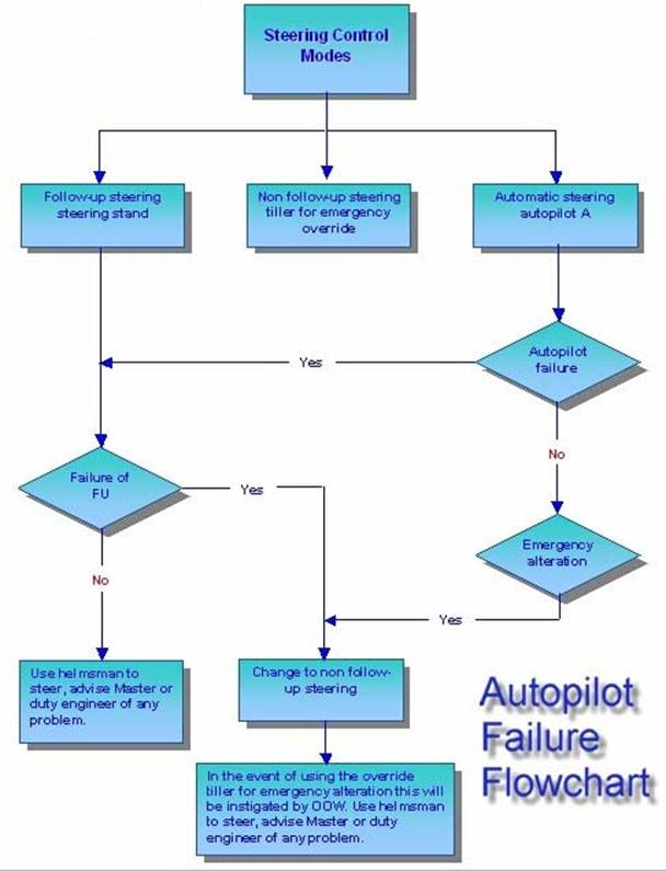
In addition to the above failures the following are
also to be noted:
At any likelihood of close/ heavy traffic the controls
should be switched to manual. Especially if in open sea when
passing a ship on end to situations, or when overtaking or when being
overtaken.
All transit through TSS should be on manual steering. Any passage where the course line is close to hazards, when the
reaction time would be in sufficient to take emergency measures, the steering
should be on manual. In heavy seas the vessel if allowed to steer a
slightly yawed course prevents damage to the fore part. And it is prudent to
switch to manual and meet the wave crests as they come in.
An example of a collision would give a better idea:
The master of a container ship off in the TSS off Cabo de Finisterre left the
Bridge at
The 2nd officer and the helmsman were on
watch. The steering was fine and the 2nd officer after some time
went into the chart room to correct charts. Around 0200 hrs the helmsman who
had doubled as the lookout reported that the ship ahead was very close since
the lights were very bright. The 2nd officer rushed out and was
dazed by the bright lights of the stern of the other ship. The other vessel was
fine on the port side of the own vessel. He instantly ordered hard a starboard.
The helmsman swung the wheel to starboard – he then reported that the steering
was not responding. The 2nd officer then ordered hard a port – panic
had set. He then realised that the vessel was still on autopilot. As soon
as the control was switched to manual the ship swung to port – since the helm
had already hard to port. The vessels collided. The port bow of own vessel
slammed into the starboard quarter of the tanker ahead of them and both
sustained serious damage.
The above highlights the need to have controls
switched over to manual well in time to prevent any such mishap.