Echo Sounder and Speed Log
Speed Logs
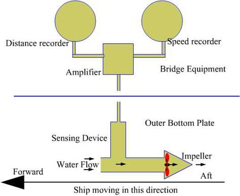
The Impeller Log
This type of log is usually fitted in small crafts.
The standard equipment consists of the following
1. The
log tube assembly
2. The
amplifier
3. Speed
indicator and distance counter
The sensing device is at the end of a long-tube or
probes, consisting of a small device called impeller (the dynamic element could
be either a small propeller or a paddle or a screw) at the end of the probe,
which is lowered into the water.
The tube is set with the port (opening) facing
forward.
The water flow drives (or turns) the impeller and the
rotation of the impeller induces an electrical signal,
which is picked up at the coils. The output is fed to the amplifier and is used
to operate the speed indicator. The rotating impellor's signal could also be
used to provide a distance measurement.
When speed (or distance) measurement is required, the
log is lowered into the water, and when not in use, is retracted inside the
hull. Retraction of the log can be done manually or by a remote hoisting
arrangement operated from the navigating bridge or engine room.
The log-tube may become blocked or obstructed by
foreign bodies such as small fish, seaweed etc. The arrangement allows the
whole tube to be withdrawn inside the vessel for inspection and cleaning. In
the event of the log-tube being bent by hitting an underwater obstruction such
as a sand bank or a large fish or more often caused by a wire or a rope having
passed under the vessel, the log-tube must be jettison.
This type of log can give only speed through water and is greatly affected by the current flowing under the ship.
The
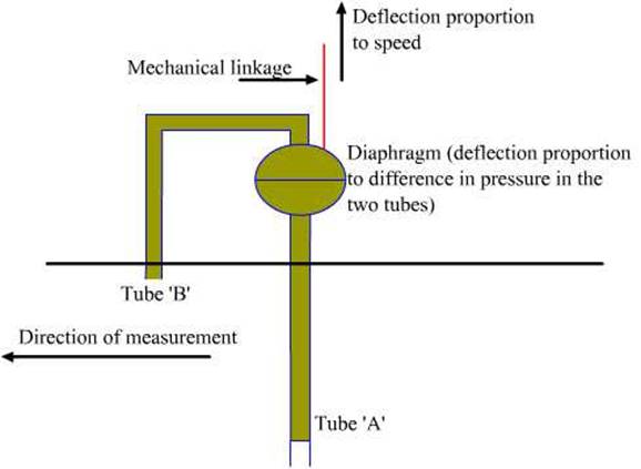
Pressure type log (Pitot tube Log)
This type of log consist of
1. Two
openings outside the hull of the ship, static tube that provides static pressure
and impact or Pitot
tube that measures dynamic pressure or the water flow of pressure
2. Controller
unit (pressure differentiator)
3. Speed
and distance transmitter
4. Speed
and distance recorder
Operations
The opening of the Pitot
tube faces forward so that when the vessel moves forward, the water causes a
pressure at the tube this dynamic pressure is proportional to the speed at
which the vessel moves. The pressure differentiator measures the differential
pressure. The Controller unit converts the pressure difference into speed and
distance units.
This type of log can give only speed through water and
is greatly affected by the movement of the water which would induce an extra
pressure giving rise to error in readings.
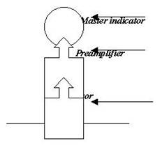
ELECTRO
MAGNETIC LOGS
This type of log consist of
1. Master Indicator
2. Preamplifier
3. Sensor
Operations
The sensing of speed makes use of law of
electromagnetic induction
When the ship moves, the
water passing through the hull acts as a conductor.
The magnetic field is produced by a solenoid,
installed in such a way as to allow the field to extend into water
This produces an EMF (electromagnetic force), which is
measured and converted into the speed of vessel through the water.
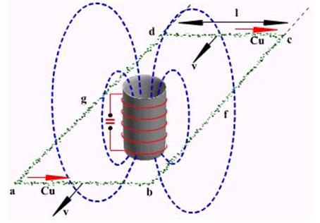
Principle
The
electromagnetic log is based upon the Faraday-Maxwell induction law; Figure shows the principle of the
log.
The induced e.m.f. ‘E’ is
given by the following:
E = F
x L x V
Where F = the magnetic field
L =
the length of the conductor
V =
the velocity of the conductor through the magnetic field.
In the EM log a direct current through the windings of
a coil, generates a magnetic field. If the conductors do not move relative to
the coil they do not intersect the magnetic fines of force and no voltage is
induced in them.
In the EM log the ‘F’ and ‘L’ are maintained constants, therefore the induced e.m.f.
is directly proportional to the velocity ‘V’, which is the velocity of the
vessel through the water.
The direction of the voltage E depends on the
directions of the lines of force and the direction of the velocity of the
conductor water. According to the formula the induced voltage is proportional
to the velocity V.
Should the velocity have the opposite direction, the
direction of the voltage would change too.
The electromagnetic log is based upon the
Faraday-Maxwell induction law;
A direct current through the windings of a coil, generates a magnetic field.
Four conductors (ab, bc, cd and da) are arranged in the
form of a loop around the coil.
If the conductors do not move relative to the coil
they do not intersect the magnetic lines of force and no voltage is induced in
them.
Alternating current through the coil
Instead of a direct current, suppose that we send an alternating current through the coil.
Then the induced voltage that we will have would be also an, alternating
voltage with amplitude that is proportional to the velocity, V.
For the electromagnetic log an alternating voltage is
preferred to a direct voltage.
The speed out put from an EM log depends upon the
water flow by way of the sensors. Thus siting of the probe is critical. This is
so since if too close to the hull then due to the non-linearity of the hull
form the speed of the water flow may give a wrong representation of the vessels
speed. This is minimized by careful siting of the sensor as well as by
calibrating the instrument while installation.
Pitch and roll also give rise to errors however these
are reduced by having an electrical time constant that is longer than a period
of vessel motion.
A well-adjusted log can have an accuracy of better
than 0.1 percent of the speed range
This type of log can give only speed through water and
is greatly affected by the current flowing under the ship. However if the water
is stationary at an anchorage there will be no speed shown.
In all the above logs the flow of
water past and under the hull play a major part in the accuracy of the
readings.
DOPPLER LOG
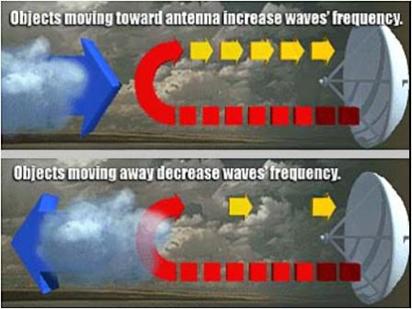
Examples of the Doppler phenomenon with sound:
The Doppler principle is the effect, which makes the
tone of a fire engine change as it passes the observer.
The fire engine is continuously emitting sound waves
but if it is moving towards the observer the wave fronts arrive closer
together, which is equivalent to a higher frequency.
As the fire engine starts to move away from the
observer, the wave fronts arrive less frequently at the observer and the tone
is of a lower frequency.
As the train approaches a stationary listener, the
pitch (frequency) of the rumbling sound of the train is higher than when the
train passes by, at which time the pitch sounds the same as if the train were
stationary.
As the train recedes from the listener, the pitch
decreases.
Electromagnetic waves radiated by radar, as well as
sound waves, obey the Doppler principal, although electromagnetic waves travel
at the speed of light and audio waves travel at the speed of sound.
The Doppler effect is a
frequency shift that results from relative motion between a frequency source
and a listener.
If both source and listener are not moving with respect to each other
(although both may be moving at the same speed in the same direction), no Doppler
shift will take place.
If the source and listener are moving closer to each
other, the listener will perceive a higher frequency - the faster the source or
receiver is approaching the higher the Doppler shift.
If the source and listener are getting farther apart,
the listener will perceive a lower frequency - the faster the source or
receiver is moving away the lower the frequency.
The Doppler shift is directly proportional to speed
between source and listener, frequency of the source, and the speed the wave
travels.
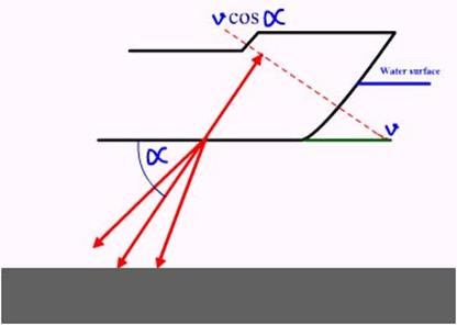
In above figure ‘v’ is the velocity of sound, and the
propagation speed is ‘ c’, every wave is shortened due
to the movement of the source by ‘d’
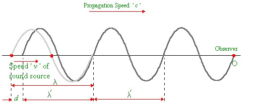
This
shortening is equal to the source having moved a distance during the time
required to generate the wave.
The Doppler log is based on measurement of the Doppler
effect.
It is
seen that an observer, moving with a source of sound towards a reflecting
plane, receives a frequency:
Where fv is the received
frequency, f the transmitted frequency, c
the speed of sound and v the speed of the source of sound.
By measuring fv and knowing f and c, the speed of a ship with regard to the seabed can be determined.
Principle
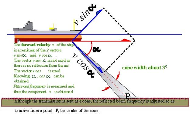
A transmitting transducer below the ship continuously
emits a beam of sound vibrations in the water at an angle (usually 60˚ to the keel) in the
forward direction.
A second transducer aboard receives the echo caused by
diffuse reflection from the seabed.
A Doppler log uses a higher frequency than an echo
sounder.
Advantages:
1.The resulting
shorter wavelength leads to the more diffuse reflection desired; the echo from
a specular reflection would not be received, in view
of the oblique incidence of the beam.
2.The shorter
wavelength makes possible a smaller beam-angle and so avoids the dimensions of
the radiating face of the transducer becoming too large.
3.The emitted
power of the sound vibrations spreads less and thus the echo is stronger.
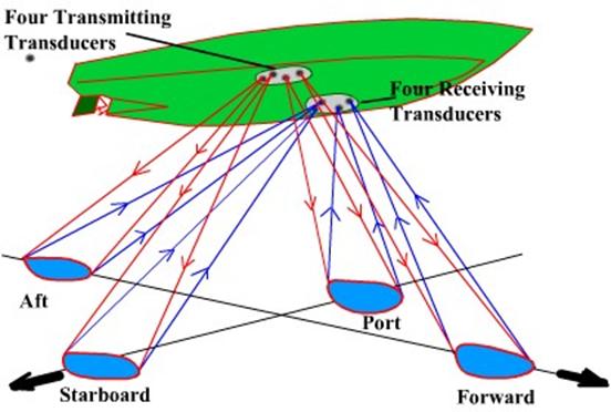
Every point of the seabed is hit by the beam and
causes a stronger or weaker echo in the direction of the receiving transducer.
All these points are situated at a different angle a
to the horizontal direction;
The frequencies received aboard must differ for all these points. However, the average frequency is approximately that from point P, at an angle a to the horizontal.
Hence, though
the distance between the ship and the seabed does not change, the received frequency will differ (owing to the Doppler effect) from the
transmitted frequency.
From the Doppler frequency-shift, which can be measured, the speed v of the vessel
can be found.
A second transmitting transducer directs a beam in a
backward direction and a second receiving transducer receives its echoes.
The speed of sound waves in the water ‘c’ depends,
however, on the temperature and (to a smaller degree) on the salinity and the
water pressure.
For that reason a thermistor
is mounted near the transducers. (A thermistor is a
resistance, the magnitude of which depends on the, temperature.)
Deviations of the sound speed ‘c’ from the normal
value are passed to the system computer for correction of its calculations.
Note that the reading of a Doppler log depends solely
on the speed of the sound waves;
The
propagation time of the pulse and its echo plays no role.
Automatic correction for changes in speed of sound
In some types of Doppler log, c/cos. α is
automatically kept constant. This is
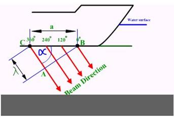
done by building up each transducer from a large number (144) of electrostrictive elements.
For simplicity only four elements are shown:
If the four elements were supplied with alternating
voltages in phase, the, resulting sound waves would also be in phase, and the
beam would be directed perpendicular to the radiating face of the transducer,
i.e. vertically.
However, the elements are fed with voltages that
differ in phase by 120°, so the sound waves have the same phase
difference.
At all points of the line AB, however, the sound
vibrations are in phase.
Such a line
or plane is called a wave front; propagation is always perpendicular to a wave
front
Reflections
Both the echo sounder and the Doppler log react to
reflections of sound waves from the seabed; the former measures the propagating
time and the latter the difference of the two frequencies.
If the beam is propagated from one water layer into a
second one of different composition or temperature, there will be reflection;
there will also be a Doppler effect if the second layer moves relative to the
first layer and if the beam hits this layer obliquely.
In that case the frequency of the sound vibrations
penetrating the second layer will also change, if the speed of the sound waves
in the second layer is different from that in the first layer.
For the echo, however, the reverse frequency change
will occur and will cancel out the first change.
A Doppler log measures the algebraic sum of all
Doppler frequency shifts experienced by the sound on its way to the bottom (or
to a reflecting layer) and back again.
To this frequency shift must be added the shift that
arises at the transition of the transducer vibrations between the ship and the
water, and vice versa. If the beam hits the bottom (bottom lock) the total
frequency shift is, proportional to the speed of the ship with regard to the
bottom.
If there is no bottom contact, but only reflection
against a water layer, the measured Doppler shift is proportional to the speed
of the ship relative to that water layer (water lock).
Janus
configuration
The placing of the two transmitting transducers, to
produce forward and backward beams is called a Janus
configuration.
Due to the Janus
configuration a linear relationship exists between the speed of the vessel and
the measured frequency shift.
A further advantage is that vertical movements of the
ship cause equal changes to the Doppler shifts in the forward and backward
beams, so the difference remains the same.
Vertical
movements of the ship do not therefore
influence the Doppler shift.
For measuring the athwart ship speed, a similar Janus configuration is mounted at an angle of 90 deg. with
the along ships transducers;
The distance from the bridge of a large tanker to the
bows may be 250 metres, so special information about the
athwart ships speed both fore and aft is required when mooring.
In that case athwart ships transmitting and receiving
transducers are mounted both fore and aft.
Janus configuration. A term describing orientations of the beams of
acoustic or electromagnetic energy employed with Doppler navigation systems.
The Janus configuration
normally used with Doppler sonar speed logs, and docking aids employs four
beams of ultrasonic energy, displaced laterally 90° from each other and each
directed obliquely (30° from the vertical) from the ship’s bottom. This is to
obtain true ground speed in the fore and aft and athwart ship directions.
These speeds are measured as Doppler frequency shifts
in the reflected beams. Certain errors in data extracted from one beam tend to
cancel the errors associated with the opposite directed beam.
Pitching and rolling
From the figure we see that the speed for the dotted
position of the ship, and for the forward-directed beam increases to V1’; for the backward-directed beam V1 decreases to V1’’.
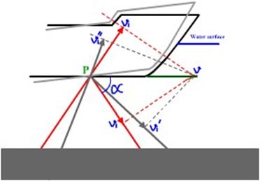
Results are obtained by taking the difference of the
Doppler shifts for the forward beam and for the backward beam.
In the horizontal position of the ship when this
vector becomes smaller this vector
becomes greater, or vice versa, so the
sum of the two vectors is approximately 2v,. Hence the
Doppler measurement of the speed is not, in practice, influenced by pitching. The
same applies to the two athwartships beams during rolling.
Continuous-wave and pulse, systems
Hitherto it has
been taken for granted that the transmitting transducers generate vibrations
continuously, thus making it necessary for each beam to have a separate
transmitting and receiving transducer.
This is called a continuous-wave (c.w.) system. Transmitting and receiving transducers are of identical construction.
Other types are pulse systems. In such a system a transducer generates
pulses and the same transducer receives the echo between the
transmissions. Therefore a pulse system
needs only half as many transducers as a continuous-wave
system.
In the continuous-wave
system the reception of the echo can be disturbed by the continuously
emitted vibrations of the transmitting transducer going directly from
transmitting to receiving transducer (cross-noise or feedback).
With pulse systems this cannot occur, since a pulse is
transmitted only after the echo of the preceding pulse has been received, and
the receiver is blocked during the transmission.
The majority of Doppler logs in use are pulse systems
Transducers
The angle of the along ships beams is about 3 deg.,
that of the athwart ships beam is about 8
degrees.
The frequency used is 100 to 600 kHz – newer models
have a transmission frequency of maybe 2 MHz.
The surface area of each transducer need then be only about 10 cm2.
The high frequency and the concave shape of the
surface also lead to a small beam angle.
The higher frequency influences the reflection and the absorption but not the speed of propagation.
The transducers are of the electrostnctive
type.
Two possibilities for a Janus configuration.
Usually the transducers are inserted in a 'sea chest'
or 'sea well’, permitting their
removal for repairs or replacement without the ship requiring dry-docking.
The diameter of the hole required in the hull plates
is about 350 mm.
Replacement of a transducer (1) in a sea chest without
the ship being dry-docked can be done in the following way.
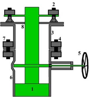
After the transducer (which is connected to the other
apparatus by means of a cable with a plug and socket) has been disconnected,
some nuts (2) are loosened and the bolts turned in the direction of the
arrows. Now the transducer (1) can be
drawn upwards until it is above the flange (4) in the upper part (3) of the sea
chest. This upper part is then shut off
from the lower part (6) by means of a sliding valve operated by the hand wheel
(5). In order to check that the valve is
properly shut a tap (not shown in the figure), connected to the upper part (3),
can be opened. If the water in the upper
part is not under pressure the bolts (7) of the flange (4) may be removed. By using grease, the transducer can be slid
easily from the top flange (8). The
sequence is reversed when a new transducer is mounted.
Measurement of ship's speed relative to bottom or to
water
Owing to absorption by particles in the water at a
depth of 200 to 400 metres, the so-called deep
scattering layer (DSL), a Doppler log may only function, down to about 200
metres, unless the set is equipped to work in the layer of 10-30 metres below
the surface.
When reflections are received from this layer the speed of the ship relative to that layer, and not relative to the bottom, is obtained. Thus uncertainty and confusion may occur.
Apart from the effect of the Deep Scattering Layer,
the water at 10 to 30 metres below the keel also causes an echo and Doppler effect by volume-reverberation.
This is called 'water track' (as opposed to 'bottom track'). In deep water there is a considerable difference between the time of propagation for bottom reflection and that for reflection from the mass of water at a depth of 10 to 30 metres. Receivers can be made operative for only a short period (a certain 'window' of time) either immediately after or a short time after each pulse transmission.
Suppose that the receiver has bottom contact, with the
window occurring a short time after,
transmission.
If the Doppler log then loses bottom contact, the
window is automatically shifted to occur immediately after pulse
transmission.
As a result, the receiver reacts only to reflections
from the 10-30-metre water layer.
When this happens, 'bottom track' indicator is
replaced by 'water track'.
When sufficiently low frequencies are used, echoes may
still arrive from a rocky bottom at a depth of 600 metres and more.
In some Doppler log, for depths less than 600 metres it is possible to switch manually to the water track mode.
Uses of the Doppler log
For, example, for a tanker of 200 000 tonnes with a
residual speed when tying up of 0.2 knots (0.1 m/s), the energy to he absorbed
by a pier or dolphin together with the ship's side is:
1/2mv2 = 1000 000 joules.
The Doppler log can measure the speed to the nearest 0.01 knot or 5 mm/s; unfortunately, however, it sometimes does not function correctly during docking if the screws of tugs cause air bubbles (which reflect sound waves) to pass through the beams (aeration). Since the sound waves are reflected off by the water – air barrier the Doppler may give wrong readings.