| Controls | Display | Errors | Antenna | Plotting |
RADAR
CRT
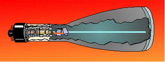
THE CATHODE-RAY TUBE (CRT)
The cathode-ray tube (CRT) and the picture tube of a
television set are one and the same.
All CRT’s have three main elements: an electron gun, a deflection system, and a
screen.
The electron gun provides an electron beam, which is a
highly concentrated stream of electrons. The deflection system positions the
electron beam on the screen, and the screen displays a small spot of light at
the point where the electron beam strikes it.
THE ELECTRON GUN
The cathode of the electron gun in the CRT is required
not only to emit electrons, but also to concentrate emitted electrons into a
tight beam.
The cathode of the CRT consists of a small diameter
nickel cap. The closed end of the cap is coated with emitting material.
CRT cathode.
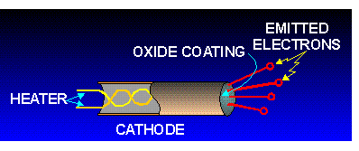
Because of this type of construction, electrons can only be emitted in one direction. Notice that the emitted electrons are leaving the cathode at different angles. If these electrons were allowed to strike the screen, the whole screen would glow.
Since the object of the electron gun is to concentrate
the electrons into a tight beam, a special grid must be used.
This special grid is in the form of a solid metal cap
with a small hole in the centre.
The grid is placed over the emitting surface of the
cathode and charged negatively in relation to the cathode.
The dotted lines represent the direction of cathode
emitted electron repulsion, as shown in the figure:
Operation of the CRT grid.
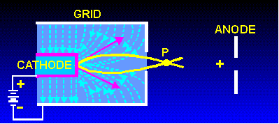
Since all emitted electrons leave the cathode (point
C), their paths can be identified. An electron attempting to travel from point
C to point B (downward) will instead follow the path from point C to point E to
point P.
Consider an electron leaving from C in the direction
of point A (upward). Its path will be curved from point C to point P by
electrostatic repulsion.
These curving electron paths are due to the negative
potential of the grid coupled with the high positive potential of the anode.
The potential of the anode attracts electrons out of the cathode-grid area past
point P toward the screen.
The grid potential may be varied to control the number
of electrons allowed to go through the control-grid opening. Since the
brightness or intensity of the display depends on the number of electrons that
strike the screen, the control grid is used to control the brightness of the
CRT.
Electron-beam formation In a CRT.
The proper name, BRIGHTNESS CONTROL, is given to the
potentiometer used to vary the potential applied to the control grid. The
control grid actually serves as an electron lens. It is this electronic lens
that is adjusted when the brightness control is turned on, on the Radar set.
Notice that the effect of the grid is to focus the electron beam at point P. After passing point P, the electrons start to spread out, or diverge, again. Therefore, it becomes necessary to provide some additional focusing to force the electrons into a tight beam again.
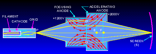
This is done by two additional positively charged
electrodes as shown in figure. The first electrode is commonly called the
FOCUSING ANODE.
Generally, the focusing anode is charged a few hundred
volts positive with respect to the cathode. Electrons emitted by the cathode
are attracted to the focusing anode. This is the reason that they travel through
the small hole in the grid.
The second electrode, called the ACCELERATING ANODE,
is charged several thousand volts positive in relation to the cathode. Any
electrons approaching the focusing anode will feel the larger electrostatic
pull of the accelerating anode and will be bent through the opening in the
focusing anode and will travel into the area labelled
D.
You might think that once an electron is in this
region, it is simply attracted to the accelerating anode and that is the end of
it. This does not happen. Because the accelerating anode is cylindrical in
shape, the electrostatic field radiating from it is equal in all directions.
Thus, an electron is pulled in all directions at once, forcing the electron to
travel down the center of the tube.
Then, the electron is accelerated into the
accelerating anode. Once it passes the mid-point (point E), it feels the
electrostatic attraction from the front wall of the accelerating anode, which
causes it to move faster toward the front. Once the electron reaches point F,
equal electrostatic attraction on either side of the opening squeezes it
through the small opening in the front of the anode.
From there, it is joined by millions of other
electrons and travels in a tight beam until it strikes the screen (point S).
THE CRT SCREEN
The inside of the large end of a CRT is coated with a
fluorescent material that gives off light when struck by electrons. This
coating is necessary because the electron beam itself is invisible. The
material used to convert the electrons’ energy into visible light is a
PHOSPHOR.
Many different types of phosphor materials are used to
provide different colored displays and displays that have different lengths of
PERSISTENCE (duration of display).
However the CRT suffers from the effects of secondary
emission. In order to reach the screen, electrons from the cathode are
accelerated to relatively high velocities. When these electrons strike the
screen, they dislodge other electrons from the material of the screen. If these
secondary emission electrons are allowed to accumulate, they will form a
negatively-charged barrier between the screen and the electron beam, causing a
distorted image on the CRT screen.
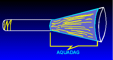
Therefore a special coating called an AQUADAG COATING
is applied to the inside of the tube. This coating is composed of a conductive
material, such as graphite, and has the same high-positive potential applied to
it that is applied to the accelerating anode. This allows the aquadag to perform two functions.
First, since the aquadag coating
is positive, it attracts the secondary emitted electrons and removes them.
Second, because the aquadag
is operated at a high-positive potential and is mounted in front of the
accelerating anode, it aids in the acceleration of electrons toward the screen.
Aquadag coating in a CRT.
To review the above:
Electrons are emitted from a specially constructed
cathode and move toward the front of the CRT. The number of electrons that
leave the area of the cathode is determined by the cap-shaped grid. In
addition, the grid concentrates the emitted electrons into a beam.
The electron beam is focused and accelerated toward
the screen by two electrodes:
The focusing anode and
The acceleration anode.
The electron beam strikes the screen and causes a
bright spot to appear at the point of impact. Any electrons released by
secondary emission are removed from the tube by the aquadag
coating.
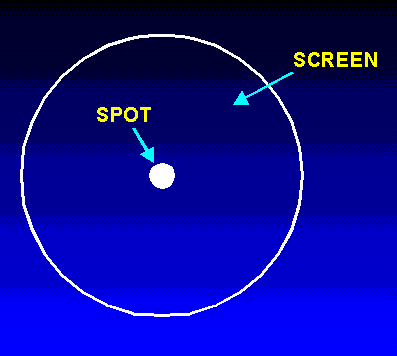
DEFLECTION
At this point, you have a bright spot in the center of
the CRT screen. For the CRT to work properly, the spot must be moved to various
positions on the screen. Because the beam is swept very quickly across the CRT
and the phosphor continues to glow for a short time after the beam has moved
on, you do not see a series of lines, but a continuous picture.
Impact of an electron beam
on a CRT screen.
Electrostatic Deflection
There are two ways to move an electron (and thus an
electron beam):
Either with a magnetic or
With an electrostatic field.
Because of this, there are three possible ways to move
or deflect an electron beam in a CRT: magnetically, electro magnetically, and
electro statically.
All three ways are used in electronics. In general,
though, electrostatic and electromagnetic deflections are used most often.
A TV set as well as a Raster scan Radar, for example,
uses electromagnetic deflection, while much of the traditional radar’s use
electrostatic deflection.
ELECTROSTATIC DEFLECTION
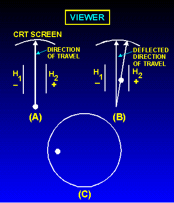
Here the electron is travelling between two charged
plates, H1 and H2. As can be seen, before the electron reaches
the charged plates, called DEFLECTION PLATES, its flight path is toward the
center of the screen.
In view B, the electron has reached the area of the
deflection plates and is attracted toward the positive plate, H2,
while being repelled from the negative plate, H1.
As a result, the electron is deflected to the right on
the inside of the screen.
When viewed from the outside of the CRT, the view
would be as ‘C’.
But to be useful, this spot will have to be converted
to a bright line, called a sweep, across the face of the CRT screen.
Horizontal deflection.

In view A, five electrons are emitted in sequence, 1
through 5, by the electron gun. The right deflection plate, H2, has
a large positive potential on it while the left plate, H1 has a
large negative potential on it.
Thus, when electron 1 reaches the area of the
deflection plates, it is attracted to the right plate while being repelled from
the left plate.
In view B, electron 2 has reached the area of the
deflection plates. However, before it arrives, R1 and R2 are adjusted to make
the right plate less positive and the left plate less negative.
Electron 2 will still be deflected to the right but
not as much as electron 1.
In view C, electron 3 has reached the area of the
deflection plates. Before it gets there, R1 and R2 are adjusted to the
mid-point. As a result, both plates have 0 volts applied to them.
Electron 3 is not deflected and simply travels to the
center of the CRT screen.
In view D, electron 4 has reached the area of the
deflection plates. Notice that R1 and R2 have been adjusted to make the right
plate negative and the left plate positive. As a result, electron 4 will be
deflected to the left.
Finally, in view E, the left plate is at its maximum
positive value.
Electron 5 will be deflected to the extreme left.
Thus what you will see when you are facing the CRT is
a bright luminous line, as shown in view E. While this description dealt with
only five electrons, in reality the line across a CRT face is composed of
millions of electrons.
Instead of seeing five bright spots in a line, you
will see only a solid bright line.
In summary, the horizontal line displayed on a CRT is
made by sweeping a stream of electrons rapidly across the face of the CRT. This
sweeping action, or scanning, is performed by rapidly varying the voltage
potential on the deflection plates as the electron stream passes.
Vertical Deflection
This is done by using a second set of deflection
plates called VERTICAL-DEFLECTION PLATES.
Arrangement of deflection plates in a CRT, front view.

In normal usage, the horizontal plates sweep a straight line of electrons across the screen from left to right while the signal to be displayed is applied to the vertical deflection plates.

Notice T1; the output of this transformer is applied to the vertical-deflection plates. The signals applied to the vertical plates are 180° out of phase with each other. Thus, when one plate is attracting the electron beam, the other will be repelling the electron beam. Because you are only concerned with what happens inside the CRT, this circuitry will be eliminated and only the CRT and its deflection plates will be shown, as in view B.
Vertical deflection in a CRT.
Now look at view C. While this illustration looks
complicated, don’t let it worry you. You have already analyzed more complicated
diagrams. The sine wave in the center of the screen is the signal that will be
displayed as a result of the two 180° out-of-phase sine waves applied to the
vertical-deflection plates. The five spots on the center sine wave represent
the five electrons used to explain horizontal deflection. Only now these
electrons will be deflected both vertically and horizontally. Time lines T1
through T5 represent the time when each like-numbered electron reaches the area
of the deflection plates. Because you already know how the electron beam is
swept or deflected horizontally, we will not discuss horizontal deflection.
Just remember that from T1 to T5, the electron beam will be continuously moved
from your left to your right. Now that you know where everything is on the
illustration, you are ready to discover how a sine wave is displayed on a CRT.
At time 1 (T1), the sine waves applied to both
vertical-deflection plates are at their null points, or zero volts. As a
result, electron 1 is not vertically deflected and strikes the CRT at its
vertical center. At time 2 (T2), the sine wave applied to the top plate is at
its maximum negative value. This repels electron 2 toward the bottom of the
CRT. At the same time, the sine wave applied to the bottom plate is at the most
positive value, causing electron 2 to be attracted even further toward the
bottom of the CRT. Remember, the beam is also being moved to the left. As a
result, electron 2 strikes the CRT face to the right of and below electron 1.
At time 3 (T3), both sine waves applied to the vertical-deflection plates are
again at the null point, or zero volts. Therefore, there is no vertical
deflection and electron 3 strikes the CRT face in the center of the vertical
axis. Because the electron beam is still moving horizontally, electron 3 will
appear to the right of and above electron 2. At time 4 (T4), the sine wave
applied to the top vertical-deflection plate is at its maximum positive value.
This attracts electron 4 toward the top deflection plate. The upward deflection
of electron 4 is increased by the negative-going sine wave (at time 4) applied
to the bottom deflection plate. This negative voltage repels electron 4 upward.
Thus, electron 4 strikes the CRT face to the right of and above electron 3. Finally, at time 5 (T5) both input sine waves are again at zero
volts. As a result, electron 5 is not deflected vertically, only
horizontally. (Remember, the beam is continually moving from right to left.)
While this discussion is only concerned with five
electrons, vertical scanning, or deflection, involves millions of electrons in
a continuous electron beam. Instead of seeing five spots on the CRT screen, you
will actually see a visual presentation of the sine wave input.
The field of electronics is in a constant state of evolution. Transistors replaced most vacuum tubes. Transistors were replaced by integrated circuits (ICs). Of all the tubes discussed, the CRT is the least likely to be replaced in the near future.