| Controls | Display | Errors | Antenna | Plotting |
RADAR
Sections of a RADAR
Essential
sections of a basic receiver and display
Antenna
drive unit; rotates the antenna at constant speed
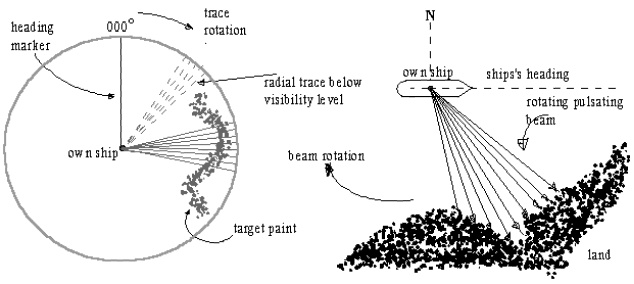
Heading
marker switch; closes when main beam is in line with ship’s head and
causes the PPI heading mark to appear
Bearing
transmitter; driven by the antenna which transmits electrically the
antenna beam bearing information
Electronic
switch (T/R cell): or the transmit/receive cell (T/R), switches at high
speed between transmit and receive modes: essentially a receiver protection
device
The receiver circuit of the Radar is an extremely
sensitive part of the receiver as it deals with signal voltages of an extremely
low value.
The voltages of the received echo signal may be as low
as a millionth part of a volt. The receiver must therefore amplify the signal
by anything between 1 and 10 million times, so as to produce adequate voltages
to be displayed onto the CRT.
The echo signals that are received have however the
same frequency as the transmitted pulse as well as the same shape (envelope) as
that which was imparted to the transmitted pulse by the modulator and pulse
forming circuit.
The weak echo signals; with the high frequency have
now to be amplified; however the amplification of signals with such high
frequencies is extremely difficult. As such the frequency (I.F.) that is
finally amplified is a much lower frequency (between 45-60MHz, depending on the
manufacturer) but the shape of the pulse remains the same.
How do we get the lower frequency – the Intermediate Frequency (I.F.)?
The process that is used is that, the incoming weak
signal is mixed with another signal of nearly the same frequency. This signal
is generated within the radar unit in the Local
Oscillator.
Thus the local
oscillator – single cavity resonant oscillator – generates a single
frequency, which is mixed in the mixer
circuit with the incoming weak echo signal. The frequency generated in the L.O. is very close to that generated by
the magnetron.
The frequency obtained from the local oscillator can
and is changed by two specific controls – one a coarse control and the other a
fine control.
The coarse control is control of the physical size of
the cavity – done by the manufacturer or at the time of installation by the
technician.
And the fine control is exercised by small variations
in the electronic conditions associated with the resonant cavity – done by the
radar operator – mariner.
Mixer; an
electronic circuit which converts the incoming echo signal at the transmission
frequency to a much lower value known as the intermediate frequency (IF); since
it is easier to process later.
9445 MHz – from the echo, same as the transmit
frequency
9505 MHz – from the Local Oscillator
= 60 MHz – Output of the mixer (IF) – this is
amplified.
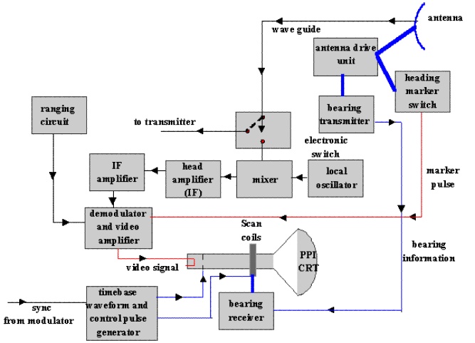
Local
oscillator; provides a frequency stable output signal having a value of
frequency either higher or lower than the transmission frequency by a value
equal to the IF.
Simultaneous application of the local oscillator
output and the echo signal to the mixer will produce a difference frequency,
which is the IF.
The IF signals contains the same information as the
incoming echo signal
Demodulator;
produces video pulses from the IF signal pulses
Video
amplifier; amplifies and processes the video pulses to a level adequate
to intensity modulate the PPI CRT beam current
Timebase waveform
and control waveform generator; generates the timebase
sawtooth sweep waveform and other rectangular waveform used to control the
display of targets during the sweep time only: the
circuits are synchronized to the transmitted pulse
Bearing
receiver: a small machine, which receives antenna-bearing information
and applies mechanical drive to rotating scan coils. The coils rotate in synchronism with the
antenna. There are also other methods of
producing a rotating scan at the PPI
Ranging
circuits; two separate circuits one of that produces periodic short
pulses to display accurately spaced concentric rings on the tube face (Range rings), the other circuit produces
a variable radius ring (variable range
marker) linked to an accurate range scale.