| Controls | Display | Errors | Antenna | Plotting |
Radar
Antenna
Antenna beamwidth and gain
Ships are designed specifically to detect targets,
which are lying virtually in the horizontal plane. The antenna therefore propagates in a
fan-shaped beam, narrow in the horizontal plane and relatively wide in the
vertical plane.
Since the antenna has direction in a particular
direction, it is said to have a power
gain in that direction. Antenna gain
is an important radar parameter and power gain in particular is considered in
the radar equation.
Beamwidth is another
of the important criteria since it specifies boundaries within the antenna
radiation pattern, which are considered to be the limit of useful radiation (or
reception).

Above shows the concept of beamwidth. This shows that because the beam
shape of a radar antenna is not conical with the cone apex at the antenna,
there exist two important beamwidth figures.
One is in the horizontal plane, known as the horizontal beamwidth (HBW) and the other is in the vertical plane, being known as the vertical beamwidth
(VBW).
The HBW tends to assume more importance than the VBW
because of its effect on the radar’s bearing discrimination.
The VBW however is large due to the fact that the
target has to be hit by the beam even in a rough sea condition, when the ship
is rolling. And also minimize unwanted echoes from the surface of the sea
whilst optimizing the power gain characteristics of the antenna.
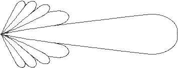
In the above it is seen a target which is struck by a
portion of the Radar beam. The bold line shows the useful main lobe of the
radiation. Power measured at A, B, C and
D is one-half the measured power at the main lobe axis along which maximum
radiated power acts. These (and other
points lying on the ellipse ABCD), are
known as the half-power points within
the beam.
Beamwidth defined;
the decibel; minor lobes
The horizontal or vertical beamwidth
is then conveniently defined as the angle subtended by the selected half-power
points at the antenna. The half-power points are also known as the minus three decibel points or three decibels down points, written -3dB
and meaning 3 decibels lower than the maximum power measured at the main lobe
axis at range R.
Vertical beamwidth (VBW) is
generally between 22-25 degrees and horizontal beamwidth
(HBW) generally between 0.8-1.5 degrees.
Note that the main transmitted lobe or major lobe does not contain all the transmitted power. Minor radiation
lobes (side lobes) also exist, but the powers in those lobes are greatly
reduced. Such a power reduction in normal circumstances causes no effect on
echoes from a distant target. However sidelobes do cause
secondary echoes, particularly from targets at short ranges. Slotted
waveguide antennas minimize such lobes.
Relationships between HBW and VBW for slotted
waveguide antennas are shown above. Also
shown is the relative sidelobe power level relative
to the main lobe axis at ± 10 degrees from that axis.
Antenna size HBW degrees VBW degrees Sidelobes± 10
degrees
12’ S
band 1.85 22 -28
dB
12’ X
band 0.65 22 -30
dB
9’ X
band 0.85 22 -29
dB
Antenna
aperture or effective area
Generally
for a given wavelength, increasing the aperture will increase the power gain and decrease the horizontal beamwidth.
Azimuth bearing transmitter and receiver
It is a small machine driven via a gear train from the
antenna drive unit. The machine is the
electrical bearing transmitter.
The machines send to the display, the bearing
information from the antenna to the display.
Antenna siting
The antenna should be placed in a position that avoids
or minimizes obstacles presented by the ship’s structure in the path of the
radiated beam. Such obstacles produce
shadow sectors and blind areas, which can hide targets of navigational
importance and give rise to false echoes appearing on the PPI.
Antenna height above sea level is also of importance,
since it has an effect on the radar horizon; in principle, radar range
improves with height. A practical limit
is reached when the incident angle of the vertical beam lobe extremities
becomes sufficiently acute to return strong echoes from the sea surface which
increases sea clutter at the display and can obscure targets at close
range.
There is also a practical limitation placed on the
amount length of the waveguide run.
Antenna height
The RF wave an effect known as diffraction by introducing slight differences in the velocity
components at different parts of the wavefront.
Diffraction causes the path of the wave to follow the
earth’s curvature for a distance determined by such factors as frequency,
surface conductivity and atmospheric permittivity. The diffraction effect is greater for lower
propagation frequencies and ten-centimetre wavelengths will bend to follow the
earth’s surface for a greater distance than will three-centimetre wavelengths,
other factors being equal
Very small targets close to the ship which might
otherwise be easily discriminated may not adequately be irradiated by the main
beam if the antenna height is too great; this and the increased sea clutter
return can cause such target return to be lost on the display.
Aerial Rotation Rate:
As per the IMO performance standards the antenna
should rotate at a constant speed of not less that 12 rpm in winds up to
100 knots.
Let us assume that an antenna rotates at a rate of 12
rpm –
Thus it rotates at 12 rotations in 60 seconds.
Or we can say that it does 1 rotation in 5 seconds.
Now if we have a Horizontal Beam Width (HBW) of 2°,
then the time required to sweep through this 2° of HBW would take:
From the above:
1 rotation in 5
seconds
: 360° in 5 seconds
: 2° in (5/360) x2
: 1/36
And from this we can derive that the time required to
sweep through the HBW (or any angle) would take:
T = HBW (or any angle) / 6 N where N is the rpm of the antenna, and T is the required time
period.
Also the number of pulses striking a target of
negligible width would be (theoretically) given by:
S = PRF x T where
S is the number of pulses and T is the time period.
Combining the two we have:
S = PRF x (HBW/6N)
So if we have a PRF of 1000pps and a HBW of 2° and a scanner
rotation speed of 12 rpm
Then the number of pulses that will theoretically
strike a point target would be:
S = 1000 x (2 / 6x12)
=
1000 x (1/36)
= 28
pulses nearly
However in general at strike rate of 10 pulses is
supposed to be great in sending back satisfactory number of echoes (some
returning pulse would not be directed towards the scanner).
If this be so and if we assume that the HBW of a Radar
set is at the limit of the IMO performance standard of 2.5° and the PRF is at
1000 pps, then the antenna rotation speed will
be - using the above equation:
10 = 1000 x (2/6N)
Or N = 33.3 rpm
For the Heading Mark on a Radar,
the IMO performance standard states that it should not be more than 0.5° thick.
The heading mark should be displayed with an error of not greater than +/- 1°.
The Slotted Wave Guide Aerial:
From physics: If an alternating signal is applied
across the mid length of a slot in a sheet of conducting material, then this
slot would act as a effective radiator of electro magnetic wave. However this
is provided that the frequency of the applied signal corresponds with the
wavelength that is twice the length of the slot.
This effect is utilized in the slotted wave guide
antenna where a number of vertical slots are cut on one side of the wave-guide
itself.
The slots interrupt the pattern of the alternating
current flow along the wall of the wave-guide and thus a signal is effectively
applied across the centre of each slot.
The slots are cut at equal interval such that the
signals all emit out in the same phase. The slotted wave-guide antenna thus
constitutes a large number of radiators having a uniform phase distribution
across a plane aperture.
This
produces a pattern as follows:
Since the wave guide is fed with the alternating
signal from one end the horizontal beam width pattern will be rotated by a
small amount away from the feed end of the guide, such that the axis of the
main lobe will make a horizontal angle of about 3° to 4° with the normal of the
slot aperture.
This angle is frequency dependent and is known as the
angle of squint.
The slotted wave guide antenna is preferred over other
types of antenna because of the ability to produce direct emission and to offer
higher aerial gain by reducing the power radiated in the side lobes.