| Load Lines | Rudder & Propeller |
Ship Construction
Ship Dimensions and Form
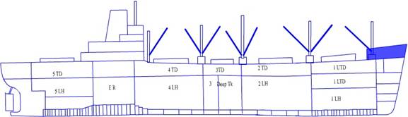
General Cargo Vessel
These types
of ships in general are built with longitudinal framing at the decks and in the
double bottoms. Transverse framing is at the sides.
Profile
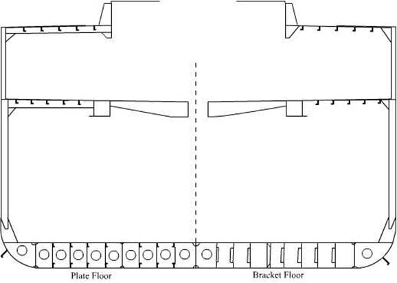
The
transverse strength is given by fitting transverses at the deck and plate
floors are fitted in the double bottoms.
Longitudinal
framing is not usual in general cargo vessels due to the high broken stowage
involved. Also deep transverses then have to be fitted about 3.7 metres to give
the ship transverse strength.
Bilge wells
are fitted with a cubic capacity of 0.17 cbm. Nowadays ceiling on top of tank
tops are generally not fitted as such the plating is increased by 2mm. However
where ceiling is fitted they should be removable in sections. The ceiling where
fitted should have a clear space for drainage at least of 12.5mm.
Cargo
battens are fitted to the sides and to the turn of the bilges – size of 50mm
thick and spacing between rows of 230mm.
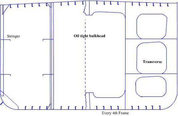
Midship
Shown above
is a centre line bulkhead in the lower hold and in the tween deck. This extends
from the transverse watertight bulkhead to the hatch coamings.
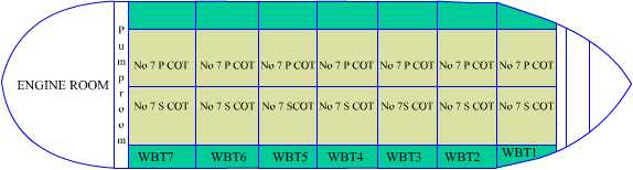
Tankers
These ships
may have two or more longitudinal bulkheads – today with double hull concept at
least 3 but normally 4.
The bottom
and deck are also framed longitudinally and so are the sides and the sides of
the longitudinal bulkheads.
The length
of a tank is not to exceed 0.2L. As the size of the tanker grows transverse
wash bulkhead are fitted at about mid length of the tank. These are for size of
tanks over 0.1L or 15m whichever is more.
Centre line
was bulk heads are fitted where the breadth exceeds the dimensions as laid out
in the Rules for different size of tanks.
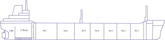
Cofferdams
are provided both forward of the oil carrying space as well as in from of the
ER bulkhead. Generally the pumproom is located within the cofferdam aft. Some
ships have a forward pump room located in the forward cofferdam.
The
cofferdams are to be at least 760mm in length
Some
smaller ships have a combined transverse and longitudinal framing system.
In lieu of
bulwarks these ships are to have open rails on deck.
Cargo tanks
are tested by a head of water in the cargo tank – 2.45m above the highest point
of the tank.
Generally a
system of staggered test is undertaken. Alternate tanks are filled and the
empty tanks is inspected. Once all the empty tanks are
inspected, the filled tanks are empties and the reverse tanks are filled and
the other alternates inspected.
Inspecting
of the tank welding are done by rafting within a tank.
Profile
Plan
Midship
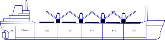
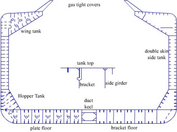
Bulk Carriers:
These ships
are characterised by their ability to carry cargo in bulk. If carrying grain
and other lighter cargo all the holds are filled.
However if
heavy cargo such as iron ore is carried then alternate holds are filled and to
the designed loads only.
Profile
The vessel
may be constructed on the combined system, longitudinal framing together with
transverse framing which are fitted at the sides. The longitudinal framing is
fitted in the double bottoms, the deck and the bottoms of the wing tanks.
The wing
tanks may be utilised to carry cargo as well as remain empty. They carry
ballast water during the ballast passage.
Transverse
webs are fitted at in the wing tanks at intervals as laid out in the Rules. And
side stringers are fitted at about 1/3rd and 2/3rd the
depth of the tanks.
Plan

Midship
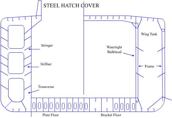
Combination Carriers:
These ships
are capable of carrying ore as well as oil in bulk.
Transverse
bulkheads are usually of the cofferdam type with all the stiffening on the
inside.
There is a
rise of floor of the inner bottom which facilitates drainage to the drain well
arranged on the centre line. The pipelines run through a duct keel. The duct
keep entrance in the pumproom has a oil and gas tight
door.
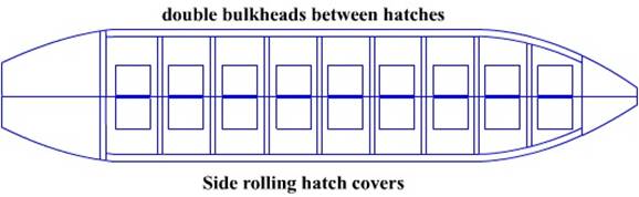
Profile
On the top
the hatch covers are mainly the side rolling Macgregor type.
The hatch
breadth is usually about 50% of the breadth of the beam. The main disadvantage
of this type of ship is the stability – since they are not built with a
longitudinal partition in the centre the free surface effect is enormous and
this necessitates overall loading complexities.
Plan
Together
with this is the sloshing effect which tend to damage
the fitting inside.
The
stability book would give the loading levels as well as the loading stability
requirements as per the Rules.
Midship
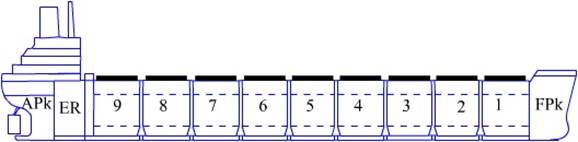
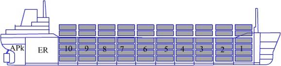
Container:
Longitudinal
framing is used throughout the main body length of the ship. Transverse framing
is used on the fore part and the after part.
Profile
The ships
are built having a cellular construction at the sides. Strong longitudinal box
girders are formed port and starboard by the upper deck – the second deck – top
of the shell plating and top of the longitudinal bulkhead. The upper deck and
the sheer strake form the box girder. These girders also provide stiffness
against racking stresses and used as water ballast tank spaces.
Midship
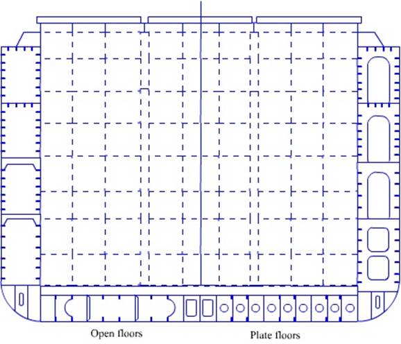
A form of
bulkhead is fitted at intervals, centre to centre with water tight bulkheads
being fitted as required by the Rules. The bulkhead gives support to the double
bottom structure.
The
container guides consist of angle bars about 150mm x 150mm x 14mm thick
connected to vertical webs and adjoining structure spaced 2.6m apart. The
bottom of the guides is bolted to brackets welded to the tank top and beams.
The brackets are welded to doubling plates, which are welded to the tank top.
Ro – Ro
Roll on Roll off ships have generally two ramps at
either end of the ship to facilitate the loading of vehicles.
The main
characteristic of these types of ships is the clear decks un
interrupted by transverse bulkheads. Deck heights are sufficient to accommodate
the various types of vehicles carried.
Profile
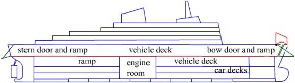
The lower
decks may be used for carriage of cars while the upper may be used for the
carriage of bigger vehicles.
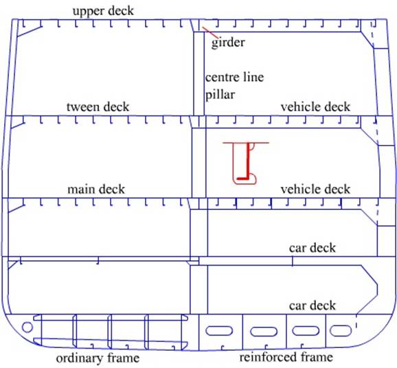
Transverse
strength is maintained by fitting deep closely spaced web frames in conjunction
with deep beams. These are usually fitted every 4th frame and about
3 m apart.
The lower
decks which are divided by watertight bulkheads have hydraulically operated
sliding bulkhead doors which are opened while working cargo in port.
The deck
thickness is increased to take the concentrated loads; a reduction in the
spacing of the longitudinals with an increase in size. A centre line row of
pillars is fitted.
Ramps are
fitted at the bow and at the stern to facilitate the loading and discharging of
vehicles. The separate decks are reached by fixed and sometimes hydraulically
operated foldable operated ramps.
A service
car is provided within the ship to transfer the lashing gear to the different
decks.
Midship
The stern
ramps are generally set at an angle to the ships centre line to ensure that the
ship can work cargo in any berth.
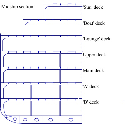
Passenger:
The basic construction of these vessels follows the
dry cargo vessel in their detail, a large number of decks being fitted.
Profile
Each passenger ship is differently built with the
naval architects and the classification societies agreeing on the various
additions to the various pillars and bulkheads.
However the basic rule and the provisions of SOLAS,
MARPOL are complied with.
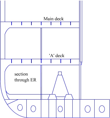
Midship
Midship in way of ER
Definitions
Camber
The purpose
of rounding the beam is to ensure a good drainage of the water and also to
strengthen the upper deck and the upper flange of the ship girder against
longitudinal bending stresses- especially the compression stresses.
Rise Of Floor
This is the distance from the ‘line of floor’ to the
horizontal, measured at the ship side. Purpose basically is to allow drainage
of the double bottom water/ oil to the centre line suctions.
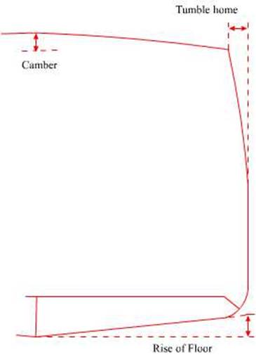
Tumblehome
This is the inward slope of the side plating from the
water line to the upper deck – today ships generally do not have a tumblehome.
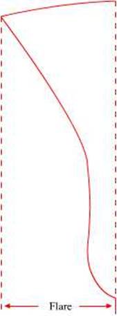
Flare
This is the curvature of the side plating at the
forward and gives additional buoyancy and thus helps to prevent the bows from
diving too deeply into the water when pitching.
The anchors are also clear when lowered from the flare
of a ship.
Sheer
This is the rise of ships deck fore and aft. This
again adds buoyancy to the ends where it is needed during pitching. For
calculating the freeboard a correction is applied for the sheer. In modern ship
the after sheer has been greatly reduced.
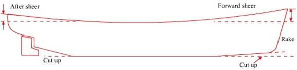
Rake
This is the
slope, which the forward end has with between the bottom plating and the upper
deck. The length between perpendiculars and the length overall difference is
mostly due to the rake forward. It helps to cut the water and thus adds to the
ships form.
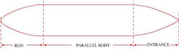
Parallel Middle Body
This is the part of the main body of the ship and it
is a box like structure enabling maximum cargo carrying capacity. It also helps
in the pushing when tugs are used to assist the vessel in berthing. Cargo
stowage is also greatly facilitated.
Entrance
This part is the fore end of the ship and helps give
the box like mid length a ship shaped structure.
Run
The after part similarly to the fore part entrance
helps in giving the box like mid length a ship shaped structure and thus the
handling of the vessel is enhanced.
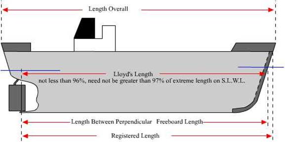
“Length” means 96 per cent of the total length on a
waterline at 85 per cent of the least moulded depth measured from the top of
the keel, or the length from the fore side of the stem to the axis of the
rudder stock on that waterline, if that be greater. In ships designed with a
rake of keel the waterline on which this length is measured shall be parallel
to the designed waterline.
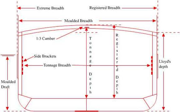
Moulded breadth: is the greatest moulded breadth –
measured inside plating.
Breadth (B) is the greatest moulded breadth of the ship at or
below the deepest subdivision load line.
Draught (d) is the vertical distance from
the moulded baseline at midlength to the waterline in question.
Depth and the draught both are measured from the top
of the keel. The depth is measure from the top of the deck beam. If there is a
camber then allowance is given as 1/3 rd of the camber.
The rest of the meanings are all
self-explanatory.
Definitions
Forward
perpendicular
This is represented by a line, which is
perpendicular to the intersection of the designed load water-line with the
forward side of the stem.
After
perpendicular
A line represents this, which is
perpendicular to the intersection of the after edge of the rudderpost with the
designed load water line. This is the case for both single and twin-screw
ships. For some ships having no rudderpost, the after perpendicular is taken as
the centre-line of the rudderstock.
Length
between perpendiculars
This is the horizontal distance between
the forward and after perpendiculars.
Length
on the designed load waterline
This is the length, as measured on the
water-line of the ship when floating in still water in the loaded, or designed,
condition.
Length
overall
This is the length measured from the
extreme point forward to the extreme point aft.
Base
line
This represents the lowest extremity of
the moulded surface of the ship. At the point where the moulded base line cuts
the midship section a horizontal line is drawn, and it is this line, which acts
as the datum, or base line, for all hydrostatic calculations. This line may, or
may not, be parallel to the load water line depending on the type of ship.
Moulded
depth
This is the vertical distance between the
moulded base line and the top of the beams of the uppermost continuous deck
measured at the side amidships.
Moulded
beam
This is the maximum beam, or breadth, of
the ship measured inside the inner shell strakes of plating, and usually occurs
amidships.
Moulded
draught
This is the draught measured to any
water-line, either forward or aft, using the moulded base line as a datum.
Extreme
beam
This is the maximum breadth including all
side plating, permanent fenders etc.
Extreme
draught
This is obtained by adding to the draught
moulded the distance between the moulded base line and a line touching the
lowest point of the underside of the keel. This line is continued to the FP and
AP, where it is used as the datum for the sets of draught marks.