| Load Lines | Rudder & Propeller |
Ship Construction
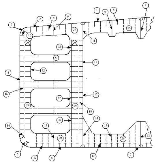
Structural components on ships’ plans and drawings:
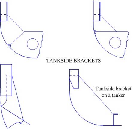
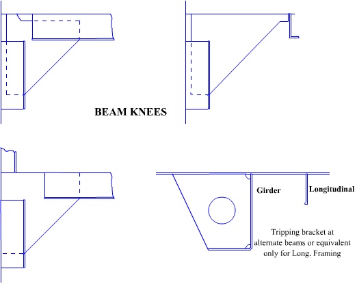
frames, floors, transverse frames, deck beams, knees, brackets, shell plating,
decks, tank top, stringers, bulkheads and stiffeners, pillars, hatch girders
and beams, coamings, bulwarks
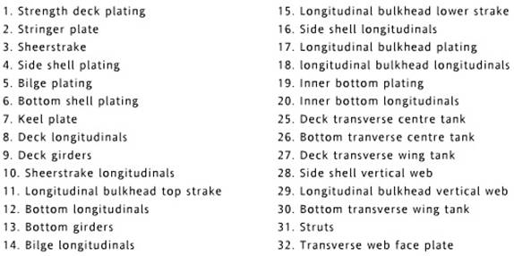
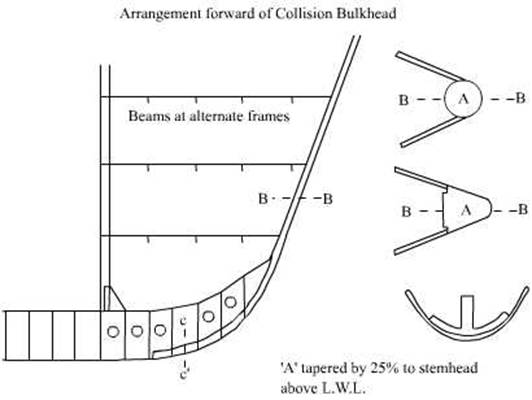
Bow and stern framing, cant beams, breasthooks
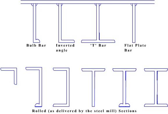
Description
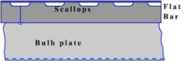
of standard steel sections: flat plate, offset bulb plate, equal angle, unequal
angle, channel, and tee
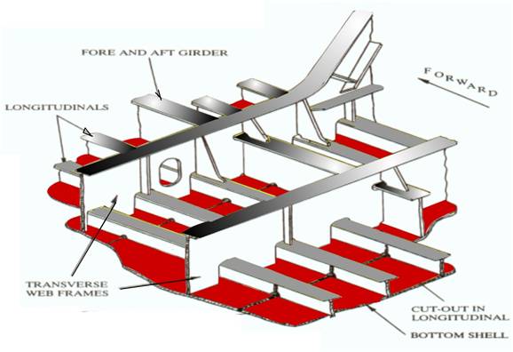
Longitudinal,
transverse and combined systems of framing on transverse sections of the ships
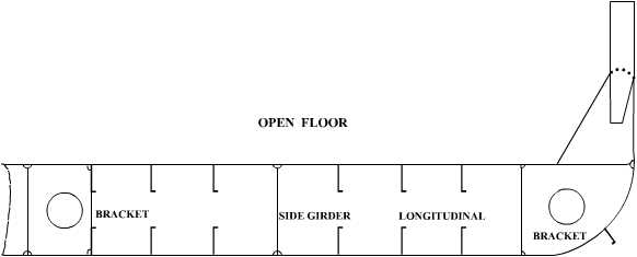
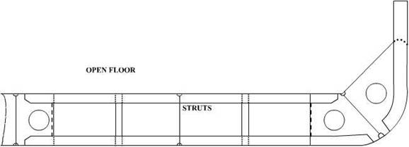
Longitudinal framing – Open floors
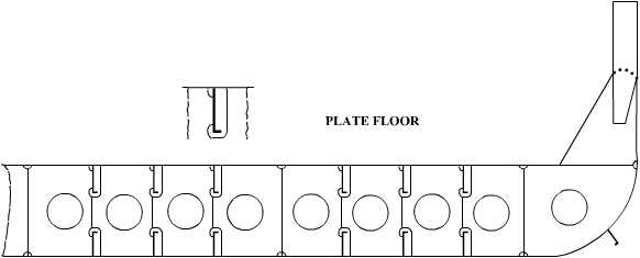
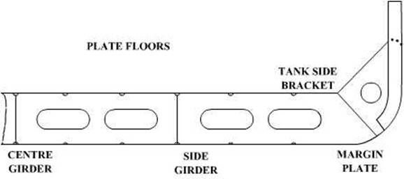
Longitudinal
framing – Plate floors
Transverse framing – Open floors
Transverse framing – Plate floors
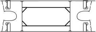
Duct keel
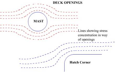
Stress
concentration in the deck round hatch openings
Holes cut in the deck plating by way of hatchways,
masts and others create areas of high local stress due to lack of continuity
created by the opening.
Compensation for loss of strength at hatch openings
Compensation around some of these openings may be overcome
by increasing the sizes of the material used, buy a careful disposition of the
material and by paying careful attention to the structural design.
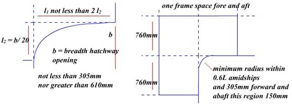
Compensating for the stress concentration around hatch
corners by rounding off the square hatch corner ends
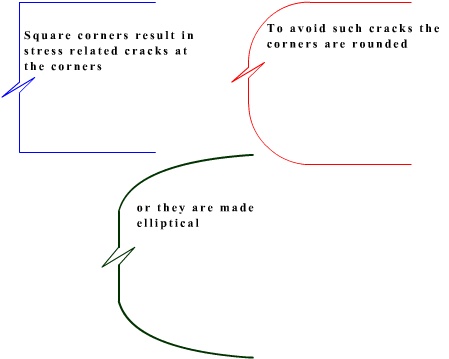
The corners radiused to reduce the stress
concentration
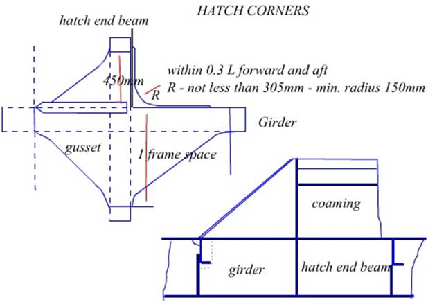
A hatch corner in plan view, showing the structural
arrangements
A transverse section through a hatch coaming, showing
the arrangement of coamings and deep webs
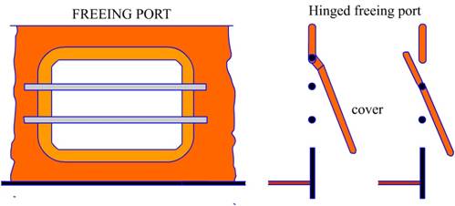
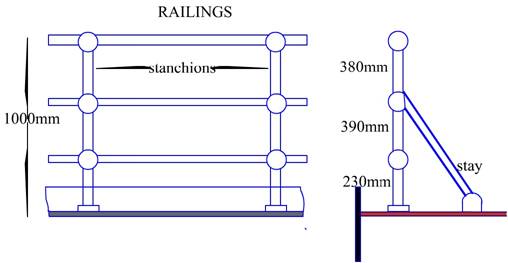
Deck‑freeing
arrangements - scuppers, freeing ports, and open rails
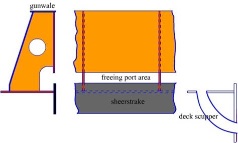
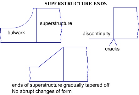
Connection of superstructures to the hull at the ship’s side
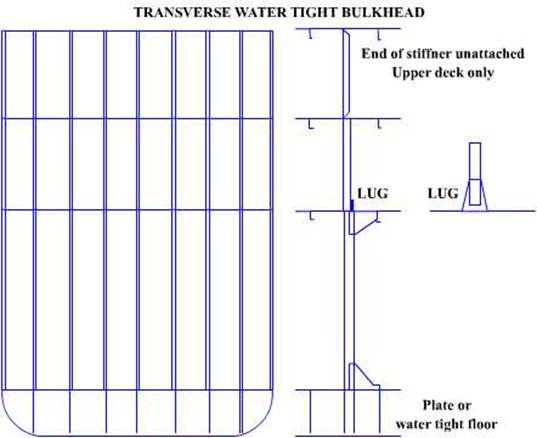
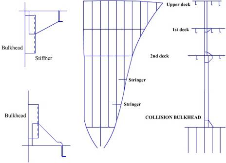
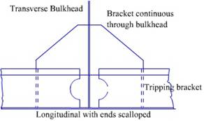
A plane bulkhead, showing connections to deck, sides and double bottom and the arrangement of stiffeners
A corrugated bulkhead
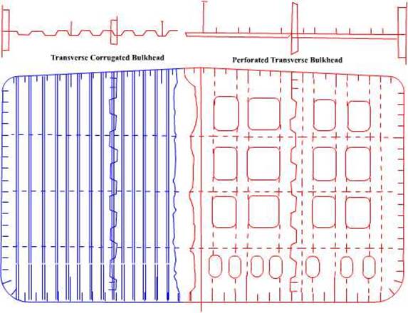
Transverse
bulkheads have vertical corrugations and fore and aft bulkheads have horizontal
ones
The basic idea of a bulkhead in addition
to the water tight integrity is to add to the girder strength of the ship beam.
Thus for a transverse bulkhead, which
extends from the port to the starboard side or vice versa, the framing is done
in a vertical manner so that the compressive and the tensile stress may be
reduced for the beam.
Similarly for a longitudinal bulkhead
which runs parallel to the shipside the framing is done vertically, again so
that the additional strength would enhance the stress compensating effect of
the ship beam.
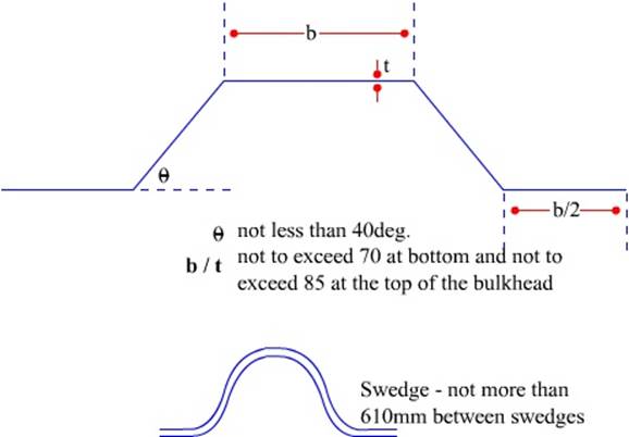
Construction
of the corrugated bulkhead
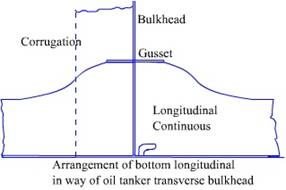
A fitted corrugated bulkhead
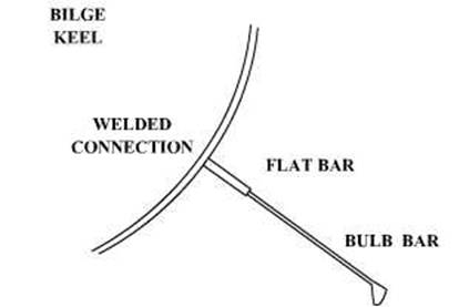
Purpose of
bilge keels and their attachment to the ship’s side
Bilge keels are fitted at the turn of the bilge to resist rolling. They also improve the steering qualities of the ship – though very slightly.
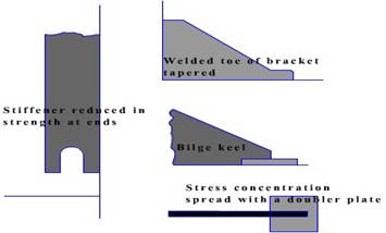
The ends are to be gradually tapered and should not
end on an un-stiffened panel.
Stress relieving while fitting the bilge keel
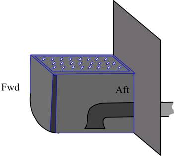
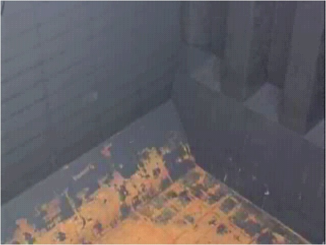
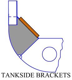
Hold drainage systems
The hold drainage system of older cargo vessels had limber board covered upper side of the tank side bracket areas. The drainage conduit was these areas and the pipelines were connected to the after ends, which passed through the lightening holes in the DB’s.
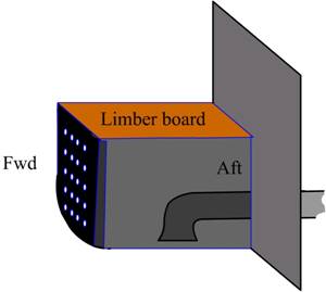
The limber boards were removable for cleaning as they
were frequently damaged (edges) leaving gaps through which cargo residue would
accumulate.
Modern ships do not have the side bilges and have only
a strum box at the after end of the holds and these are connected in the
similar way to pipelines, which run through the DB’s.