| Grain Cargo | Cargo Care | IMDG | Cargo Handling Equipment | Cargo Handling Safety | |
| Oil Tanker | Cargo Measurement | Enclosed Spaces |
Cargo Work
Draft, Trim and Stability
The Load Line Marks
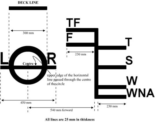
LR – the symbols of the classification society (Lloyds Register) by the side of the Plimsoll mark
TF – Tropical Fresh (water) F – Fresh Water T
– Tropical (Sea Water)
S – Summer (Sea Water) W – Winter (Sea Water)
WNA – Winter
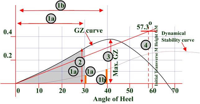
Criteria of
Stability:
Extract from the Load Line Rule (1968)
The area under the curve of Righting Levers shall not
be less than:
0.055 metre-radians up to an angle of heel of 30˚
0.09 metre-radians up to an angle of heel of 40˚
0.03 metre-radians between the angles of heel of
30˚ and 40˚
The Righting Lever shall be at least 0.20 metre at an
angle of heel equal to or greater than 30˚
The maximum Righting Lever shall occur at an angle of
heel not less than 30˚
The Initial Transverse Metacentric Height (GM) shall
not be less than 0.15 metre
Ship
Stability – working with ‘kg’, TM, Draft, Displacement and Trim including LCB
and LCF
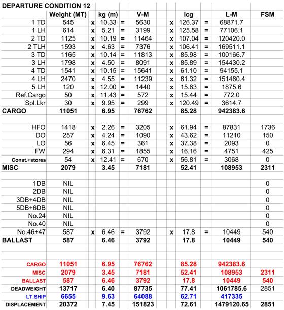
Method of working:
The following example shows how a ships stability
booklet has pre-determined conditions of loading and the consequent stability
criteria.
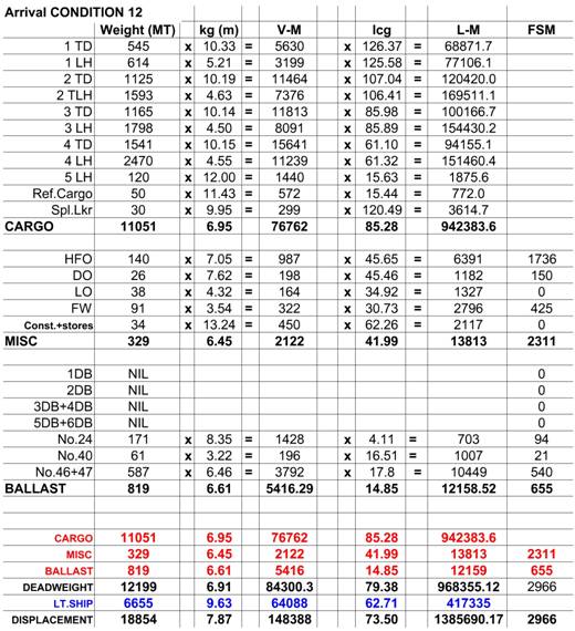
The said condition is 12; each ‘Departure’ condition
has an ‘Arrival’ condition.
In the Departure condition the vessel is assumed to be
sailing out with a load of cargo and with full bunkers and stores. The ballast
is negligible.
In the Arrival condition the vessel is assumed to have
arrived her disport/ way port (may be bunkering for long voyage), here the
cargo remains the same only change is in the bunkers and FW.
The Arrival condition is to be worked out prior
departure since the arrival condition determines the loading of the cargo.
Since no vessel would like to arrive a port in a critical condition – not
satisfying the stability criteria.
The weight is multiplied with the ‘kg’ of each
compartment to obtain the vertical moments.
These are added up (all – cargo, ballast, Bunkers and
light ship) and the total of the V-M is divided by the displacement to get the
final KG
In the same way the weight is multiplied with the
‘lcg’ of each compartment to obtain the longitudinal moments. These are added
up (all – cargo, ballast, Bunkers and light ship) and the total of the L-M is
divided by the displacement to get the final LCG.
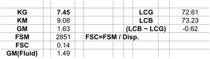
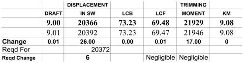
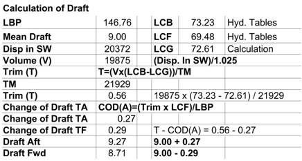
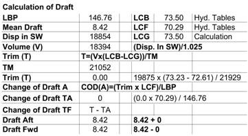
Noting the Displacement the tables are referred to
obtain the LCB, Mean Draft and the Trimming Moment. With these inputs the final
drafts and the GM is calculated.
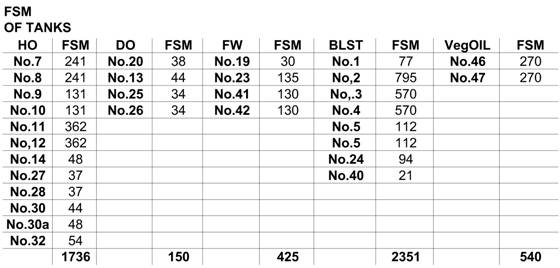
For obtaining the Fluid GM, the FSM of the
compartments are read off from the tank data sheets.
The total of the FSM when divided by the displacement
gives the FSC that is to be subtracted from the GM to obtain the GM (F).
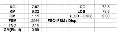
The following shows the departure condition of a ship,
the general particulars are given.
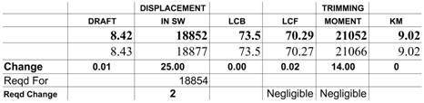
And the following gives the arrival condition for the
same ship – the cargo is the same, only change being the fuel and the ballast.
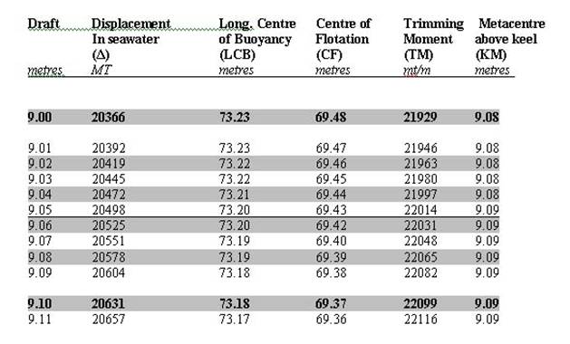
The
following are extract from the hydrostatic table of ship ‘A’.
Given that the morning draft in sea water of ship ‘A’
is Forward: 8.92m and Aft: 9.12m
Ship ‘A’ loads cargo throughout the morning shift and
her sailing drafts are:
Fwd: 8.99m, Aft: 9.19m
To find the amount of cargo loaded. Note, during the
morning the ship received H.O. bunkers – 100MT and consumed 10MT of FW.
Morning Mean Draft: (8.92 + 9.12)/ 2 = 9.02m
Sailing Mean Draft: (8.99 + 9.19)/ 2 = 9.09m
Displacement at 9.02m: 20419
Displacement at 9.09m: 20604
Thus the difference in displacement would be: (20604 –
20419) = 185 MT
Bunkers received: 100MT
FW consumed: 10MT
Thus the cargo loaded would be: 185 – 100 = 85 MT
(correcting for the bunker) and
85 + 10 = 95MT (correcting for the FW consumed)
For change of trim the earlier example is to be
referred.