| Grain Cargo | Cargo Care | IMDG | Cargo Handling Equipment | Cargo Handling Safety | |
| Oil Tanker | Cargo Measurement | Enclosed Spaces |
Cargo Work
Oil Tanker
A tanker is a specialized ship intended for the carriage of bulk liquid cargo. An Oil tanker again is further divided into 2 basic types, namely Crude Oil Tanker and Product Oil Tanker.
For both of the above the cargo of oil is carried
within the tanks similar to the holds of other ships, the difference being that
the bulkheads are extra strengthened to take in the load, and the hatch or
rather the tank openings are very small, the sole purpose of having them is for
Man Entry and for small repair work in the dry docks.
The cargo of oil is loaded on to the ships tanks by
pipelines, which are fixed on the ship (permanent structure), the shore
pipelines are connected to the ships pipelines at the manifold on either side
of the ship. Note that some special ships also have manifolds at the bow and at
the stern.
The shore pipelines may be connected using flexible
steel rimmed rubber hoses (small ports/ Ship to ship transfers/ SBM) – the
flexible come in small lengths are connected to each other to make them long
pieces.
The shore pipelines may also be connected with rigid
loading arms – also called ‘chiksons’, which are remotely controlled and take
in the roll of the ship to a certain extent but the fore and aft movement of
the ship has to be kept to a minimum.
The combined pipeline system of the shore and the ship
deliver the oil to the cargo oil tanks directly via the drop lines. These are
as the name suggests pipelines, which drop to the bottom of the tanks
vertically from the pipeline on deck – thus bypassing the pump room.
There are various cross- over valves, which are opened
in order to load a group of tanks.
The shore system starts to pump/ delivers by gravity
(some
To prevent this surge from affecting the pipelines the
cargo valves have set times at which they close – this depends on the size of
the valves – typically a 550mm valve would shut at about 24 seconds, whereas a
250mm valve would shut at 6-8 seconds.
After the ship completes her loading the stage is set
for the unloading or discharging operation.
While loading the cargo had by passed the pump room,
now however the cargo from the tanks is allowed to flow to the pump room
through the bottom pipelines. Just within the pumproom and at the pumproom
bulkhead are situated isolation valves known as ‘Bulkhead Master valves’, by
opening the valves the oil is led to the pump suction valve and on opening that
the oil flows to the centrifugal pumps. Turbines, which are situated in the
Engine Room, commonly drive these pumps; the shaft penetrates the ER bulkhead
and drives the pump situated at the bottom of the pumproom.
The pump accelerates the flow of the oil into the
discharge pipeline and this oil is thus led on the deck pipelines and to the
manifold from where it flow through the flexible pipeline or the hard loading arm
to the shore pipeline system.
The Pump Room
This is a cofferdam kind of space – in fact it is
accepted as a cofferdam, which begins on main deck and ends at the keel.
It may have more than 2 decks, however these decks are
not normally solid decks but are partial decks made of expanded metal, so you
are able to see right to the bottom.
There would be a companionway leading from the top to
the next deck and so on right to the bottom.
At the lowermost deck are situated the Cargo Oil Pumps
(COP’s). The numbers of pumps vary in number – for crude oil tankers it is
normal to have 4 pumps, three being used at any one time.
For product oil tankers the number of pumps depend on
the number of grade of oil that the ship is capable of carrying.
So if the ship can carry 4 grades of oil then she
would be having 4 pumps.
Once the gravity flow to the COP’s is not possible the
stripped pumps are started, these pumps are of the reciprocating type and have
great capacity to create partial vacuum to suck out the remaining oil from the
tanks. Again on a product oil tanker the number of stripped pumps would be
equal to the number of grades of oil that it can carry.
Earlier on Crude oil carrier there would be stripper
pumps of the reciprocating type however today largely eductors are used to
remove the remaining oil from the tank. Generally 2 eductors are provided on
each crude oil tanker. However 1 stripper pump is always provided to strip the
cargo lines of any residual oil and to pump the same to the shore system.
The pumproom is a hazardous area as such the light
fittings are gas tight and only tanker safety torches are used. The ventilation
system is of the exhaust type and has intakes from all the levels with the
intakes being fitted with closing devices so that if required only a certain
level can be evacuated.
Hydrocarbon gases being heavier than air tend to
settle at the bottom of the pumproom as such the main exhaust are always from
the bottom level.
The pumproom lighting is devised in such a way that
the lights do not come on unless the ventilation has been started and is kept
on for 15 minutes.
AT the top of the pumproom a harness and lifting
arrangement is provided to lift out a person from the lowermost deck, for this
reason a clear passage is left vertically from the top to the bottom of the
pumproom.
Fire man’s outfit are also placed at the top of the
pumproom, the pumproom may have different types of fixed fire fighting
appliances such as total flooding by CO2 or by foam applicators fitted in the
bilges (below the floor plates under the lowermost deck).
Bilge alarms are fitted which give alarms when the
bilges are filled – a high level and a low level alarm is fitted which gives
indications in the Engine room as well as in the Cargo Control room.
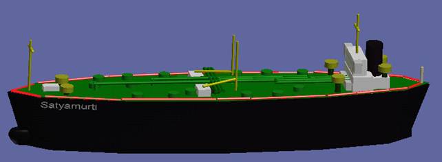
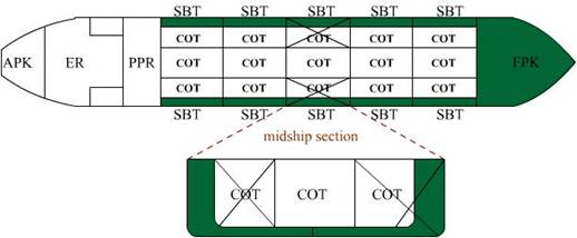
Picture shows the main deck layout of a Product tanker
(capable of carrying 4 grades of oil):
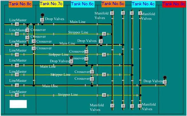
The same
tanker – with the tank layout.
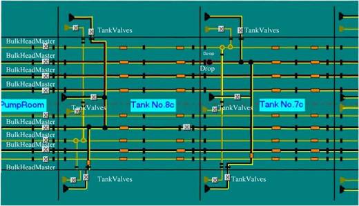
And part of the pump room layout of the same tanker.
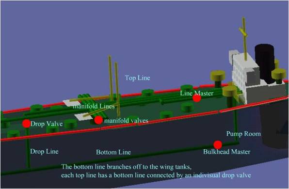
The above shows the location of the drop valves; drop
lines, line master, bulkhead master and the bottom lines.
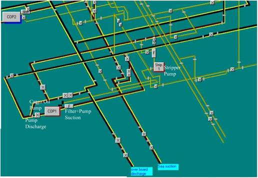
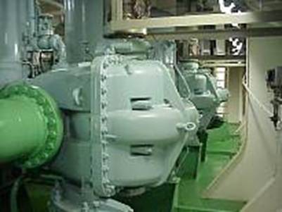
Cargo Oil
Pumps (COP)
A centrifugal pump, in the pumproom bottom platform.
The dark green pipeline is the discharge line. The pump consists of an impeller
which rotates within the casing. Due to this rotation which is generally about
1000 – 1700 rpm the oil is speeded up and this increase in velocity causes the
oil to flow out at a great pressure. These pumps are capable of delivering a
very high rate of discharge (up to 4000 m3/hr). With this type of pump the
level of oil has to be above the pump – as such the pump is situated at the
bottom of the pump room.
Another detail of the same centrifugal pump.
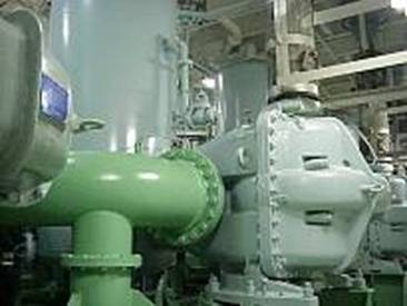
The earlier centrifugal
pump situated in the pumproom is driven by a shaft which is connected to the
steam turbine – situated in the ER. The shaft passes from the ER to the
pumproom through the pumproom bulkhead via a gas and oil tight gasket.
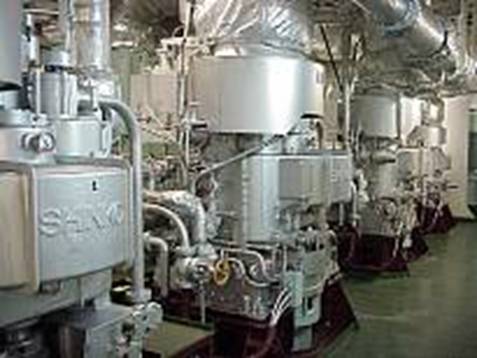
The turbines are driven
by superheated steam from the boiler in the ER.
Positive displacement
pumps such as the reciprocating pump work on the principle of a hand pump – the
movement of the piston creates a vacuum which sucks out the fluid. However the
size of the pump is dependent on the size of the piston and the length of the
strokes so for discharging at a high rate is practically impossible. In general
these pumps are used to discharge small quantities of oil such as the
strippings – the balance that the centrifugal pump cannot discharge due to the
oil going below the level of the pump. The pump is used today on crude tankers to
strip out the pipelines after discharging and then collecting these line
content (small) and then pumping them to shore.
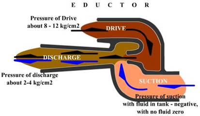
Eductors
Eductors work on the
principles of Bernoulli’s Principle.
A driving fluid is
pumped down the main line, with very high velocity, through a constriction, and
past a relatively smaller opening, thus creating a vacuum.
When eductors are used
for clean ballast, the driving fluid is seawater.
When used for stripping
crude oil, the driving fluid is the cargo itself- delivered by means of a
bypass from one of the main cargo pumps.
When used for stripping
tank washings, the driving fluid is from the secondary slop tank and then
re-circulated back to the primary slop tank. In the latter case the driving
fluid is either crude oil or seawater, depending on the tank cleaning method.
Eductors are simple and rugged, have no moving
parts, and do not become air locked like other type of pumps. They are widely
used on tankers of all types and sizes.
Tank layout
of a crude oil tanker:
The Pipeline system:
Pipeline systems on
tankers differ in their degree of sophistication, depending on employment of
the tanker.
ULCC’s and VLCC’s have
relatively simple pipeline systems usually the direct line system.
Some product (parcel)
tankers may have very sophisticated piping systems. This could be the ring main
system or in case of a chemical product tanker it could mean an individual
pipeline and an individual pump for every tank on board.
Basically there are
three systems of pipelines found on tankers, and the fourth system being the
free flow system found on large crude carriers
Ring Main System
Direct line system
Single line to Single
tank system (Chemical/Product ship)
Free Flow system
Ring Main System:
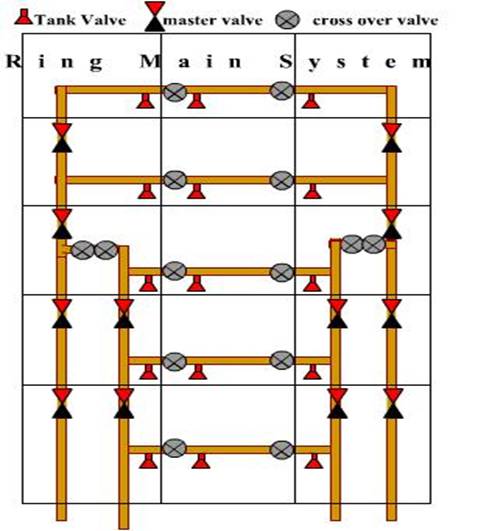
It is generally of a
square or circular layout.
It is used mostly on
product tankers, as segregation of cargo is required.
Though the system is
expensive, as more piping, and extra number valves are used.
However if the vessel is
carrying many grades of cargo, the advantages compensate for the extra cost of
the original outlay.
Direct Line
System:
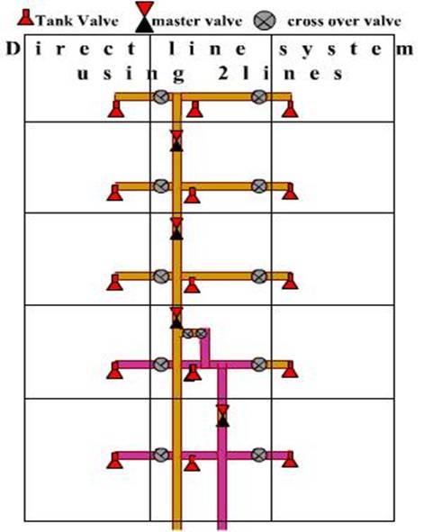
This system is mainly found on crude oil carriers
where up to 3 grades of cargo can be carried as most of the direct pipeline
systems is fitted with three direct lines.
This system is cheaper to construct. The disadvantages
over the ring main system, is that line washing is more difficult, the system
has fewer valves which make pipeline leaks difficult to control, as the system
lacks versatility there is problem with line and valve segregation.
This system provides the
vessel to carry as many grades as there are tanks.
The
disadvantage is the cost factor having a multitude of pumps on board.
Free flow Tanker:
This system is usually
found on large crude carriers, where the cargo piping is not used for the
discharge of cargo.
Instead, gate valves are
provided on the bulkheads of the tanks which when opened; allow the oil to flow
freely in the aft most tank and into the COP.
The advantages of this
system are primarily the cost factor, it allows for fast drainage and efficient
means of pumping the cargo tanks. Disadvantages are of single crude being
shipped.
Independent System:
This layout is not very
common in the tanker trade.
This system is quite
normal on chemical ships.
There are some Product
Tankers that have this system fitted on the ships.
This is a single line
servicing an individual tank through an independent pump that could be either a
submersible pump or a deep well pump.
Enclosed
Space Entry
An enclosed space is one with restricted access that
is not subject to continuous ventilation and in which the atmosphere may be
hazardous due to the presence of hydrocarbon gas, toxic gases, inert gas or
oxygen deficiency. This definition includes cargo tanks, ballast tanks, fuel
tanks, water tanks, lubricating oil tanks, slop and waste oil tanks, sewage
tanks, cofferdams, duct keels, void spaces and trunkings, pipelines or fittings
connected to any of these. It also includes inert gas scrubbers and water seals
and any other item of machinery or equipment that is not routinely ventilated
and entered, such as boilers and main engine crankcases.
Many of the fatalities in enclosed spaces on oil
tankers have resulted from entering the space without proper supervision or
adherence to agreed procedures. In almost every case the fatality would have
been avoided if the simple guidance in this chapter had been followed. The
rapid rescue of personnel who have collapsed in an enclosed space presents
particular risk. It is a human reaction to go to the aid of a colleague in
difficulties, but far too many additional and unnecessary deaths have occurred
from impulsive and ill-prepared rescue attempts.
Respiratory hazards from a number of sources could be
present in an enclosed space. These could include one or more of the following:
Respiratory contaminants associated with organic
vapours including those from aromatic hydrocarbons, benzene, toluene, etc.;
gases such as hydrogen sulphide; residues from inert gas and particulates such
as those from asbestos, welding operations and paint mists.
Oxygen deficiency caused by, for example, oxidation
(rusting) of bare steel surfaces, the presence of inert gas or microbial
activity.
Hydrocarbon Vapours
During the carriage and after the discharge of hydrocarbons,
the presence of hydrocarbon vapour should always be suspected in enclosed
spaces for the following reasons:
Cargo may have leaked into compartments, including
pumprooms, cofferdams, permanent ballast tanks and tanks adjacent to those that
have carried cargo.
Cargo residues may remain on the internal surfaces of
tanks, even after cleaning and ventilation.
Sludge and scale in a tank which has been declared gas
free may give off further hydrocarbon vapour if disturbed or subjected to a
rise in temperature.
Residues may remain in cargo or ballast pipelines and
pumps.
The presence of gas should also be suspected in empty
tanks or compartments if non-volatile cargoes have been loaded into non-gas
free tanks or if there is a common ventilation system which could allow the
free passage of vapours from one tank to another.
Oxygen
Deficiency
Lack of oxygen should always be suspected in all
enclosed spaces, particularly if they have contained water, have been subjected
to damp or humid conditions, have contained inert gas or are adjacent to, or
connected with, other inerted tanks.
Other
Atmospheric Hazards
These include toxic contaminants such as benzene or
hydrogen sulphide, which could remain in the space as residues from previous
cargoes.
ATMOSPHERE
TESTS PRIOR TO ENTRY
General
Any decision to enter an enclosed space should only be taken after the atmosphere within the space has been comprehensively tested from outside the space with test equipment that has recently been calibrated and checked for correct operation.
It is essential that all atmosphere testing equipment
used is:
Suitable for the test required;
Of an approved type;
Correctly maintained;
Frequently checked against standard samples.
A record should be kept of all maintenance work and
calibration tests carried out and of the period of their validity. Testing
should only be carried out by personnel who have been trained in the use of the
equipment and who are competent to interpret the results correctly.
Care should be taken to obtain a representative
cross-section of the compartment by sampling at several depths and through as
many deck openings as practicable. When tests are being carried out from deck
level, ventilation should be stopped and a minimum period of about 10 minutes
should be allowed to elapse before readings are taken.
Even when tests have shown a tank or compartment to be
safe for entry, pockets of gas should always be suspected. Hence, when
descending to the lower part of a tank or compartment, further atmosphere tests
should be made. Regeneration of hydrocarbon gas should always be considered
possible, even after loose scale has been removed. The use of personal
detectors capable of continuously monitoring the oxygen content of the
atmosphere, the presence of hydrocarbon vapour and, if appropriate, toxic
vapour is strongly recommended. These instruments will detect any deterioration
in the quality of the atmosphere and can provide an audible alarm to warn of
the change in conditions.
While personnel remain in a tank or compartment,
ventilation should be continuous and frequent atmosphere tests should be
undertaken. In particular, tests should always be made before each daily
commencement of work or after any interruption or break in the work.
Sufficient samples should be drawn to ensure that the
resulting readings are representative of the condition of the entire space.
Hydrocarbon Vapours
To be considered safe for entry, whether for
inspection, cold work or hot work, a reading of not more than 1% LFL must be
obtained on suitable monitoring equipment.
Benzene
Checks for benzene vapour should be made prior to
entering any compartment in which a cargo that may have contained benzene has
recently been carried. Entry should not be permitted without appropriate
personal protective equipment if statutory or recommended Permissible Exposure
Limits (PEL’s) are likely to be exceeded. Tests for benzene vapours can only be
undertaken using appropriate detector equipment, such as that utilizing
detector tubes. (Benzene causes cancer, and has a delayed action which may be
up to 20years)
Detector equipment should be provided on board all
vessels likely to carry cargoes in which benzene may be present.
Hydrogen
Sulphide
Although a tank which has contained sour crude or sour
products will contain hydrogen sulphide, general practice and experience
indicates that, if the tank is thoroughly washed, the hydrogen sulphide should
be eliminated. However, the atmosphere should be checked for hydrogen sulphide
content prior to entry and entry should be prohibited in the event of any
hydrogen sulphide being detected. Hydrogen sulphide may also be encountered in
pumprooms and appropriate precautions should therefore be taken.
Oxygen Deficiency
Before initial entry is allowed into any enclosed
space, which is not in daily use, the atmosphere should be tested with an
oxygen analyzer to check that the normal oxygen level in air of 21% by volume
is present. This is of particular importance when considering entry into any
space, tank or compartment that has previously been inerted.
Generally
nearly all substances have been assigned Permissible Exposure Limits (PEL) and
/or Threshold Limit Values (TLVs). The term Threshold Limit Value (TLV) is
often expressed as a time weighted Average (TWA). The use of
the term Permissible Exposure Limit refers to the maximum exposure to a toxic
substance that is allowed by an appropriate regulatory body.
The PEL is
usually expressed as a Time Weighted Average, normally averaged over an eight-hour period.
Short Term
Exposure Limit (STEL), is normally expressed as a maximum airborne
concentration averaged over a 15-minute period.
The values
are expressed as parts per million (PPM) by volume of gas in air. Toxicity can
be greatly influenced by the presence of some minor components such as aromatic
hydrocarbons (e.g. benzene) and hydrogen sulphide. A TLV of 300PPM,
corresponding to about 2%LEL, is established for gasoline vapours.
Entry Procedures
General
A responsible officer prior to personnel entering an
enclosed space should issue an entry permit. An example of an Enclosed Space
Entry Permit is provided in ISGOTT.
Suitable notices should be prominently displayed to
inform personnel of the precautions to be taken when entering tanks or other
enclosed spaces and of any restrictions placed upon the work permitted therein.
The entry permit should be rendered invalid if
ventilation of the space stops or if any of the conditions noted in the
checklist change.
No one should enter any cargo tank, cofferdam, double
bottom or other enclosed space unless an entry permit has been issued by a
responsible officer who has ascertained immediately before entry that the
atmosphere within the space is in all respects safe for entry. Before issuing
an entry permit, the responsible officer should ensure that:
The appropriate atmosphere checks have been carried
out, namely oxygen content is 21% by volume, hydrocarbon vapour concentration
is not more than 1% LFL and no toxic or other contaminants are present.
Effective ventilation will be maintained continuously
while the enclosed space is occupied.
Lifelines and harnesses are ready for immediate use at
the entrance to the space.
Approved positive pressure breathing apparatus and
resuscitation equipment are ready for use at the entrance to the space.
Where possible, a separate means of access is
available for use as an alternative means of escape in an emergency.
A responsible member of the crew is in constant
attendance outside the enclosed space in the immediate vicinity of the entrance
and in direct contact with a responsible officer. The lines of communications
for dealing with emergencies should be clearly established and understood by
all concerned.
In the event of an emergency, under no circumstances
should the attending crew member enter the tank before help has arrived and the
situation has been evaluated to ensure the safety of those entering the tank to
undertake rescue operations.
Regular atmosphere checks should be carried out all
the time personnel are within the space and a full range of tests should be
undertaken prior to re-entry into the tank after any break.
The use of personal detectors and carriage of
emergency escape breathing apparatus are recommended.
Reference should be made to ISGOTT for additional
guidance on entry into pumprooms.